Lab scope diagnostics

May 30, 2023
Gaining a deeper understanding of the 'why' when vehicle problems surface.

Content brought to you by PTEN. To subscribe, click here.

Automotive technicians rely on a variety of tools to diagnose and troubleshoot problems surfacing on vehicle systems. Today, we're seeing vehicles with multiple network circuits containing high-speed data communications along with advanced powertrain controls. More than ever one of the most important tools in their arsenal is the lab scope, also known as an oscilloscope. Lab scopes are electronic testing devices that allow technicians to view and analyze electrical signals and their characteristics. In this article, we will discuss real-world examples using lab scopes to troubleshoot and diagnose problems in automotive systems.

There are a few basic knowledge elements one needs to have a decent understanding of if they are going to use the oscilloscope to aid them in troubleshooting and the first and most important question you will want to ask yourself is 'why.'

Important metrics:

  • Sample rate — how often the scope is sampling the signal it is measuring.
  • Voltage levels — the expected voltage range the scope will need to measure and display.
  • Time base — the amount of time displayed on the screen.

Users need to understand that the time base setting on the scope can influence the sample rate. A slower sample rate may result in missed measurements of rapid voltage signal changes. Some scopes will allow some flexibility here where you can prioritize the sample rate within limitations. Typically, the more expensive the scope the more capable it is.

Essentially, a decent consumption of electrical circuit education along with lab scope training and network communication knowledge will provide today’s technician with the necessary skillset that will enable him or her to be successful today and well into the future. Additionally, one must always accept the fact that they are likely to find opportunities to learn more along the way through their diagnostic experiences. This will truly raise the value of your offering to the service industry and promote a strong career.

Case study No. 1: Throttle actuator control (TAC) challenges

Throttle-by-wire systems have been around for quite some time now and it’s likely you’ve already encountered complaints involving these. We had a 2013 Volvo XC60 that arrived with the following complaint:

Customer states that while driving the vehicle, they went to make a turn and the MIL suddenly came on, at that same point the vehicle seemed hesitant to shift into the next gear. The customer turned the vehicle off and started it up again, MIL light remained on but seemed to be driving normally.

The technician started the vehicle and confirmed that it appeared to be operating properly and the MIL was still illuminated.

Upon scanning the vehicle, the following DTCs were recorded within the ECM:

  • 0x7E8: P050700 - Idle air control (IAC) system RPM higher than expected.
  • 0x7E8: U016700 -Lost communication with vehicle immobilizer control module.
  • 0x7E8: P061F00 - Internal control module throttle actuator controller performance. 
Other modules reported faults (Figure 1) that didn’t seem relevant to the current complaint.
The technician proceeded to perform a vehicle inspection looking particularly at the throttle body and air intake systems since the throttle-by-wire systems are closely monitored and any airflow anomalies can trigger throttle actuator control (TAC) DTCs.
After collecting the freeze frame information, the DTCs were cleared, and several road tests were performed where zero faults were observed. The technician then removed the throttle body air inlet for inspection where he found lots of oil and carbon buildup on the throttle plate and bore. Now in most cases, folks might tend to recommend a throttle body cleaning and then place the vehicle back into service. However, we were concerned with the P061F fault and wanted to take a closer look at the power electronic controls within the throttle body assembly.
My article from October 2022, Electronic controls: Lateral and longitudinal, covered the fact that manufacturers perform TAC system checks prior to and after vehicle shutdown. These tests are used by the manufacturer to gauge system performance and to validate proper operation prior to the vehicle issuing any powertrain torque output commands. This is all done in the spirit of vehicle safety and oftentimes one can observe this behavior audibly after engine shutdown. Many vehicles will perform this analysis after a power-down cycle by running an operational script on the throttle body.
In this case, we wanted to see if the lab scope could help us look deeper into this throttle body. We consulted a wiring diagram (Figure 2) to have a look at throttle body circuits. (Note: The engine performance diagram section wasn’t immensely helpful here and we ended up finding the best diagram in the cruise control section.) Although the detail for each pin isn’t listed, we consulted the signal specifications under the engine control module (ECM) section where we were able to find that the motor control terminals were residing at pins one and two at the throttle body and pins 74 and 75 at the ECM. And TP sensor one was located at pin six at the throttle body and pin 65 at the ECM.
Next, we connected the Picoscope as follows:
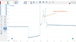
  • Channel 1 — TA473 - 60-amp current probe around the BU-GN (pin 74) wire
  • Channel 3 — 1:1 voltage probe across pins 74 and 75 so we could monitor the half-bridge controls on the brushed DC motor
  • Channel 4 — 1:1 voltage probe at pin 65 (TP1) referenced to ground
Next, we configured each channel as follows:
  • Channel 1 — +/- 10A
  • Channel 3 — +/- 50V DC
  • Channel 4 — +/- 5V DC
Our audible senses let us know that there were tests occurring after keying off, so we set the scope to record at the following settings:
  • Sweep — 2 s/div
  • Sample rate — 2.5MS/sec
Next, we turned the key to KOEO then hit record on the scope and immediately turned the key to off and stopped the scope near the end of the sweep. The following results were recorded in Figure 3
We looked hard at that signal and really couldn’t see anything glaring at us that would have indicated that there was either a mechanical or electrical problem with the throttle body. So based on the mileage and the fact that the throttle body was coked up badly with oil, we recommended a new replacement throttle body. After replacement, we proceeded to perform the same tests as before to see if we could learn anything, which we did...sort of.
The primary difference we observed was that there appeared to be a high-frequency control problem during a specific point in the system’s self-test. If you look at Figure 4, you can see what I’m referring to as compared to Figure 3. Now can we hang our hat on this? No, but I can tell you that after disassembling the motor and having a look inside, we were able to determine that we made the right call. The motor commutator and brushes were influenced by the engine motor oil that had migrated through the throttle shafts and caused heavy carbon to build up between the brushes and the commutator contacts. Figure 5 shows this detail. 
It is my opinion that the low-lying location of the throttle body within the intake tract location makes it more prone to throttle body coking. However, excessive oil could be caused by improper PCV system operation or just poor design. Throttle body service should be carried out on engines with low-mounted throttle bodies more frequently than their counterparts. Nevertheless, this vehicle is back on the road ready to continue delivering service well into the future.

Case study No. 2: Misfire analysis  — secondary ignition coil over plug, cassette coil assy.

A 2012 Chevrolet Cruze with the 1.8L arrived with the following complaints:
The customer drove the vehicle in and stated that he purchased the vehicle about two weeks ago. The MIL came on while driving home. The DTCs were checked and found a P0171 set. The customer replaced both O2 sensors (aftermarket). The water pump was also replaced. The customer states that the MIL came back on for a P0301. The customer replaced the injector on cylinder one and an ignition coil pack to correct the problem. The customer states that the MIL came back on for P0300. Inspect and advise on repairs.
The following DTCs were stored:
  • 0x7E8: PO122 - Throttle/pedal position sensor 'A' circuit low (permanent)
  • 0x7E8: P0171 - System too lean (bank one) (permanent)
  • 0x7E8: P0223 - Throttle/pedal position sensor/switch 'B' circuit high (permanent)
  • 0x7E8: P0300 - Random misfire detected (SES, pending, current, old, permanent, history)
  • 0x7E8: P0597 - Thermostat heater control circuit/open (pending)
  • 0x7E8: P0598 - Thermostat heater control circuit low (pending)
  • 0x7E8: P0689 - ECM/PCM power relay sense circuit low (pending, history)
  • 0x7E8: P1682 - Driver five line two (pending, current, history)
  • 0x7E8: P2078 - Intake manifold tuning (IMT) valve position sensor/switch circuit high (pending)
Looking at the misfire history, we could see that No. 4 was contributing to the misfire although a P0304 was not set.
Since this motor used a “cassette” style ignition coil assembly, I chose to use the Picoscope secondary ignition leads to establish a clean sample of the KV waveform for each plug wire (Figure 6).
We also wanted to use a current probe to sample both the ignition coil power supply along the fuel injectors and I found that F9UA was tasked with protecting both systems via circuit 5291 at the underhood power distribution center and used one of my fuse loops to connect a current probe. Additionally, I back-probed the cylinder one ignition coil ECM command signal as a reference (Circuit 2121).
This setup allows one to analyze both ignition and fueling events for each cylinder which is extremely helpful during misfire analysis.
As you can see in the scope capture in Figure 7, the current probe allows us to see the activity of two circuits (fuel injectors and ignition coils) within one channel, which is a huge time saver. 
The reason for this is so we can see whether the coil primary circuit is being driven on the misfiring cylinder and the reason for triggering from coil one is so I can tell which cylinder looks abnormal. My process typically has me sampling each cylinder for a few seconds starting with cylinder one and moving in cylinder numerical order. It’s clear that the No. 4 cylinder is misfiring because the secondary output is non-existent.
Zooming in on that capture allows us to take a closer look to verify the injector current and secondary current are happening for the suspect cylinder, which it was (Figure 8). 
With that level of testing out of the way, we were very certain that the ignition coil was causing the misfire. Replacement of the coil pack assembly solved the misfire problem.
Since a misfire can be caused by several items including compression, we performed a preliminary “ear-test” of the relative compression prior to deploying the scope and used it to quickly assess the ignition and fuel injector’s operation. The ignition coil that we removed from the vehicle appeared to be a genuine OEM product, but a few markings were different from the new OEM unit we sourced. It’s very possible that the coil pack assembly the customer sourced could have been counterfeit, but that’s a discussion for another day.

Case study No. 3: Intermittent blower motor operation

A 2010 Toyota Tacoma arrived with a complaint that the blower motor didn’t want to work sometimes and when it was in failure mode, the client stated that he could tap on the area below the glovebox and the blower would work. When we went to check the operation, we found that the blower would work every time we asked it to perform. So, after performing a visual inspection of the blower motor connections we decided to take a quick look at the blower motor current to see if we could gain any knowledge as to why it was intermittent. Figure 9 provides a major clue supporting the client’s statement.
The zero amperage spikes answer the 'why' question because the blower motor has such a high resistance at that section of the motor commutator that when it stops and lands on that section, we don’t have any electromotive force to “push” the blower motor to begin working. For a closer look, I zoomed in on Figure 10
As you can see the scope and a current probe were quick and highly effective in identifying a defective blower motor. And the bottom line is that the scope allowed me to definitively determine why the issue was intermittent.
Although these are just a few examples of how powerful the lab scope can be, there are far more uses and practical applications. But beware, it is equally important to know when you need to use the scope because a few basic tests can sometimes lead you to a conclusion without you needing to pick up your lab scope.  

Sponsored Recommendations

Access Carside OEM Repair Data with MOTOR TruSpeed

Now available on all Autel MaxiSYS Ultra Series tools, MOTOR TruSpeed Repair delivers expanded OEM service and repair data within days of being published by

ADAS Case Study: From 10 Calibrations a Month to Over 10 A Day

Originally published by Vehicle Service Pros, March 26, 2024

Autel MaxiTPMS TS900: 3-in-1 TPMS Tablet

Originally published by Tire Review, April 4, 2024

Ask The Expert: The Basics & Benefits of Bringing ADAS Calibrations In-house

Originally published by Vehicle Service Pros, March 26, 2024

Voice Your Opinion!

To join the conversation, and become an exclusive member of Vehicle Service Pros, create an account today!