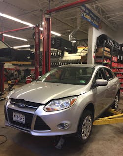
I was called to a shop for a simple task of reprogramming a new ECM on a 2012 Ford Focus with a 2.0L engine (Figure 1). There are a lot of shops in the industry that do not want the responsibility of programming a new ECM due to the liability and costs involved in doing the job. Some shops may not be properly equipped with the proper interface or laptop and may not want to go out to the Internet to fill out an application to sign up with an individual manufacturer and purchase a daily subscription. This may be coupled with a need to be registered through NASTF as a Security Professional to access theft procedures that may be needed during the post programming procedures. There is also the need to have a proper battery charger in the shop that can provide a "Programming" mode that will maintain a specific voltage range while a current surge occurs such a cooling fan coming on during the programming process. Some manufacturers will terminate programming if voltage falls below 13.1 volts or if voltage exceeds 14.0 volts. An older battery charger with only Low, Medium and High settings is not recommended and may pose a problem if too much AC ripple is introduced.
Is the ECM to blame?
When I arrived at the repair shop I proceeded to question the shop technician to see why he had made the decision to replace the ECM. It is not uncommon for a shop to jump the gun to condemn a control module without probable cause. I'm not in the business to just go ahead and reprogram a Control module at will without making sure it will resolve their issue with the vehicle. The last thing I need is to charge a shop to program a new or used control module only to find out that it was wasted revenue without a cure for their problem. I will usually question the shop to see if they followed the proper procedures to condemn the module. This would include checking power and ground feeds, shorted reference voltages, communication lines or even an issue with their testing equipment.
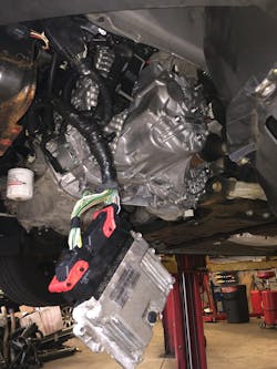
The shop told me that they just replaced the transmission (Figure 2) and when they got done the vehicle would no longer start. They checked the vehicle and found that the ECM was not responsive so they figured it might have been damaged during the repair procedure. This is a bad situation of "Drive them in / Push them out". We have all been there before at one time or another in the repair business. It becomes an unwanted marriage between you and the vehicle and your only way out is to resolve the issue at your own cost because you can't expect the customer to pay it. In the end it all becomes a learning experience but you’re under the gun to get things resolved ASAP before the customer is aware of his or her new dilemma.
When I hooked up to the new ECM to program it I was unable to communicate with it. The shop was under the impression that the new ECM would not communicate because it needed to be programmed. This is misinformation that I see a lot of shops seem to believe in and I had to school them on this belief and to educate them on how to evaluate no communication issues with a vehicle. They have to always make sure that prior to condemning a controller they check EVERY power and ground feed at the ECM and scan the entire vehicle to make sure it is not just a single control module issue without focusing too much of their attention only on one single controller. By scanning the entire vehicle they will get a better evaluation of all the operating systems that are responsible in starting the vehicle. Sometimes the clues to their problems may be resonated in other modules on board that may put them on a better path in their diagnostic process.
Start at the beginning
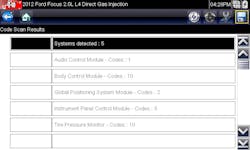
I placed my scan tool on the vehicle and did a full scan of the entire vehicle. I discovered that only five control modules were present on the multiple networks this vehicle had on board (Figure 3). These were the Audio, Body, GPS, Instrument and Tire Pressure Monitor control modules. This vehicle had three separate CAN networks on board: Medium Speed, High Speed and Entertainment CAN networks. The High Speed CAN network was inoperative. The controllers on this network included the Transmission, Engine, ABS, Power Steering, Steering Angle, Air Bag and Occupant Classification control modules. It was highly unlikely that all these control modules were bad or that they all had a common power or ground feed failure. What was common to all of them was a network circuit that was either open or shorted.
It is very important to understand how a CAN network is structured prior to testing it. Keep in mind that all the controllers wired on a single CAN network are all considered nodes and they are all wired in parallel. The CAN network consists of a twisted pair of communication lines to eliminate electromagnetic interference. There has to be a way to stabilize waveform reflection within the network and this is done by putting a terminating resister at each end of the network. A 120 ohm resistor is commonly used at both ends of the network and may be internal to a module or externally mounted on the network wiring. The 120 ohm resister internal to a control module will usually be the control modules furthest at the ends of the CAN network. If we use Ohms Law we can mathematically figure out the total resistance of the network. The total resistance of the network will always be the sum of the inverse of each individual resistance. Total resistance will also always be lower than the smallest resistance. In this case:
1/Rt = 1/R1 + 1/R2
1/120 = 0.0083
0.0083 + 0.0083 = 0.0166
1/0.0166 = 60.24
With this equation we should expect about 60 ohms across each network.
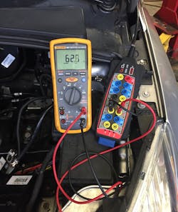
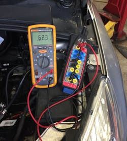
The battery would have to be disconnected prior to doing an ohm check because the system cannot be alive while using an ohm meter. I used an OBD interface box to make things easier while working under the dash. As you get older you want to work smarter without having to put too much pressure on the lower part of your vertebrae while hanging upside down under the dash. The interface has labeled ports that reflect the 16 pins of the OBD II connector and each port is coupled with LED's that alert your attention to presence of power, ground or data activity. I used my Fluke meter and tested the Medium Speed CAN network first at pins #3 and #11 and acquired a reading of 62.8 ohms (Figure 4). Then I preceded to the Entertainment CAN at pins #1 and #8 and acquired a reading of 62.3 ohms (Figure 5). These readings were well within the tolerances of a healthy CAN network.
Module or wiring?
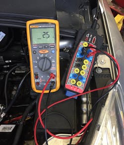
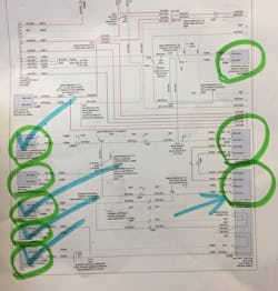
I now proceeded to check the High Speed CAN network pins #6 and #14 and acquired a reading of 2.5 ohms (Figure 6). This network was shorted together. This would make sense why seven controllers fell off the radar. The hard part now was to put together a game plan of attack to locate the source of the problem. The possibilities that could be laid out were that any one of these seven controllers could be shorting out the network or the network harness could be shorted somewhere in the vehicle. I printed out a diagram and circled the seven controllers involved and checked off the ones that were the easiest to access (Figure 7). The eighth controller was an optional Parking Aid Control Module that was not fitted on the vehicle. My plan was to unplug each controller one at a time to see if the short would be eliminated. If the problem remained then I knew I had a harness problem.
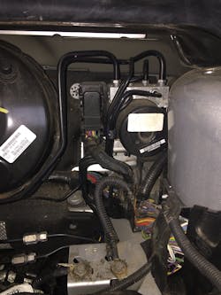
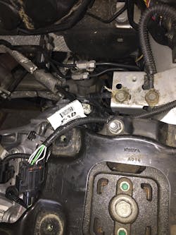
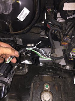
I wanted to start with the easiest controllers to gain access to without too much work involved so I went to the engine compartment first. I disconnected the engine and transmission control modules that were already exposed near the base of the transmission and there was no change. I next decided to go after the ABS control module that was located at the driver side firewall. In order to access this module I had to pull the battery out of the way (Figure 8). As I was reaching for the ABS connector I was looking down at something that caught my eye. There was a harness crushed under the battery tray (Figure 9). This was not good. I proceeded to remove the crushed harness and exposed what turned out to be damaged CAN network wires (Figure 10).
Problem found — on to the fix
The two wires that were crushed in the network connector were for the High Speed CAN network. I simply repaired the wiring and put everything back together and the vehicle started right up with no problems. It was amazing how these two wires took down the vehicle and put it out of commission during a routine R&R of a transmission assembly. These seven control modules were cut off from the rest of the vehicle as if they were stranded on Gilligan's Island away from all interaction with the rest of the crew. The seven modules were are still responsive and in good working order with good powers and grounds but were no longer able to communicate among each other or with other controllers on the network. This led to the other controllers setting "U" codes for loss of communication with modules within the networks.
Repairing vehicles today are much more difficult because you’re now working in tighter quarters and components are not always easy to get to or even remove and replace. It is so important to watch your every step to make sure things are put back the way you find them and to be very careful not to put components in harm’s way. When you experience a problem you always need to go back to where you were last. Don't be so homed in to one module problem but branch out you diagnostic routine to include a full scan of the entire vehicle to enable you to dot the I's and cross the T's.
