
This article has been updated from its original 2019 version.
In this article, I will be talking about a subject that does not get much respect or attention amongst most automotive technicians: Engine crankcase ventilation systems. Many technicians consider these systems to be pretty simple and trouble free, but they are often overlooked in their importance, as well as their ability to cause rather confusing problems on modern powertrain platforms.
Understanding crankcase ventilation
Crankcase ventilation is as old as internal combustion engines and has to be addressed in any modern, emission-controlled powertrain. Prior to federal emission control standards, the crankcase of an engine was vented to atmosphere through a component called a road draft tube. The tube was connected to the side of the engine block or valve cover and routed down to slightly below the bottom of the engine in the vehicle's slipstream.
When the car was moving, air rushing past the tube would create a low-pressure area and fresh air would enter the engine through a breather that was usually the oil filler cap. This would allow the engine blow-by gases to be drawn out of the crankcase and vented to the outside.
While simple, there were problems. When the vehicle is not moving, there is no crankcase ventilation and when driven at high speeds, the system is too efficient and oil was drawn out of the engine along with blow-by gases creating a black, oily stripe down the center of the highway. The main problem with this type of system is the release of unburned hydrocarbons into the atmosphere.
Crankcase emissions were considered one of the main causes of smog in the Los Angeles basin in the 1950s and ’60s. In 1961, Positive Crankcase Ventilation systems became mandatory in California. In 1964, all new cars were equipped with this system. PCV systems allow the combustion blow-by gases to be rerouted into the engine intake manifold to be burned with the incoming air/fuel mixture. These systems are basically vacuum controlled, so there is less flow at low engine loads when blow-by would be less and greater flow under road load conditions when blow-by increases.
Many modern powerplants have done away with the common PCV valve and now utilize fixed orifice systems or an integrated flow control valve and oil separator.
Testing crankcase ventilation system function
The first indication that something may be amiss with crankcase ventilation is an excessive amount of condensation in the crankcase. This is commonly seen during an oil change by milky deposits found on the oil fill cap or seen inside the oil fill hole.
The problems I am more concerned with is when crankcase ventilation problems create a “Check Engine” light concern, which most often shows up as fuel trim codes. One particular vehicle comes to mind that was sent to me from another shop. The 2001 Chevy S-10 Blazer with a 4.3 VIN W engine had lean fuel trim codes set for both banks. There was a disconnected vacuum hose found, but even after plugging the hose, the fuel trim numbers were very high at idle — each bank was positive 24 percent.
A new replacement mass airflow sensor had already been tried with no change in fuel trim values. Knowing that false air or unmeasured air can skew fuel trim, it was decided to disconnect the crankcase air inlet hose to see if the trim values changed at idle. They did not.
Crankcase air supply is provided after the mass airflow sensor, so this air is measured. If air is being drawn into the crankcase from a leak, then this air cannot be measured, and the system will be lean.
One final check was made. A vacuum gauge was connected to the dipstick tube and the PCV fresh air inlet (at the valve cover) was blocked with the engine idling. The vacuum reading is shown in figure 4. Almost no vacuum was present indicating there is an air leak into the crankcase. When smoke (from a smoke machine) was added to the crankcase, the problem became evident. There was an improperly installed valve cover gasket on the passenger side of the engine. Replacing the gasket corrected the high fuel trim values.
This issue has played itself out many times on different vehicles and has caused a large amount of unnecessary parts replacement because many technicians do not look at crankcase leaks as a possible cause of fuel trim codes and do not measure crankcase pressure.
Pressure, vacuum or both?
While I have been mentioning measuring crankcase pressure, what is normally seen is a negative pressure or partial vacuum. This is because a regulated vacuum is applied to the crankcase in order to draw out combustion blow-by gases. Keep in mind when taking crankcase vacuum measurements that the fresh air intake should be blocked off, and it will take a few moments for vacuum to build in the crankcase.
This brings to mind some more theory on crankcase pressure. I remember purchasing a tool long ago from my Snap-on supplier called a MT-383 Blow-by tester. This tool measured the amount of blow-by gas flow leaving the crankcase. The PCV valve was removed from the valve cover and the flow meter installed in its place. The fresh air inlet was plugged and the engine ran at both idle and high speed. The clear, graduated flow meter measured flow in standard liters per minute.
The theory is as an engine wears out, especially from piston ring and cylinder wear, there will be an increase in crankcase pressure due to greater blow-by and this can be measured to determine wear. This leads to the issue that there can be both a crankcase over-pressure condition as well as an under-pressure condition. If engine wear causes too much crankcase pressure it will overwhelm the PCV system and lead to excessive oil leaks. Excess crankcase pressure may also occur if the PCV system vacuum supply becomes restricted. Excessive crankcase under-pressure, (vacuum) can occur if the fresh air inlet becomes restricted or the wrong PCV valve is used.
Turbos and crankcase ventilation
When a turbocharger is added to the engine the crankcase ventilation system becomes somewhat more complicated. This is due to the fact that the routing of crankcase blow-by gases has to change when the engine is under boost pressure (because of the lack of manifold vacuum). I will use a case study from a turbocharged BWM to illustrate this issue.
Speaking of BMWs, these vehicles clearly display the need to measure crankcase pressures when driveability problems arise. Unlike many vehicles, BMW’s with Valvetronic intake valve lift control have a regulated intake manifold vacuum. The target vacuum level on any BMW Valvetronic engine is only 50 millibar or about 1.5 inches of mercury. With this small amount of vacuum available, crankcase pressure is closely regulated and can have a major impact on how these engines run at idle.
I use a Dwyer series 475 digital handheld manometer to measure crankcase pressure on most European cars and any BMW vehicles. The tool measures pressure in inches of water column but this is easily converted to millibar (which is the spec given by BMW). The adaptor seen in the picture is available from a company called AGA tools, or you can make a test adaptor from and old oil cap. There is a service bulletin, #11 05 98, which details testing crankcase pressure on BMW vehicles. I highly recommend printing this out and keeping it handy if you work on these vehicles.
Not only can you measure crankcase pressure with a vacuum gauge or manometer, you can also use an accurate pressure transducer such as a Pico WPS500 to measure crankcase pressure with a scope. A scope and pressure transducer may also be able to show pressure pulses inside the crankcase that can be caused by excessive cylinder wall to piston compression leakage that escapes into the crankcase.
Figures 9 and 10 show a crankcase pressure test performed on a 2016 BMW X-5 with the N55 turbo-charged six-cylinder engine. The bottom waveform is crankcase pressure and the upper waveform is cylinder #1 ignition coil firing (so you can see when the engine was started and shut off). The time-base is quite slow at 10 seconds per division. When the engine is shut off it takes an amazing 75 seconds for the pressure to return to atmospheric in the crankcase. That is a tightly sealed crankcase!

I must also mention here that while the BMW TSB is mostly concerned with too much pressure, or a lack of vacuum in the crankcase (Which would indicate a leak), there is also the problem of too much vacuum! Many engine faults on a BMW Valvetronic engine can put the engine in throttle control mode and the intake manifold vacuum will be very high, like a conventional engine. The crankcase ventilation system is not designed for high manifold vacuum so the crankcase negative pressure will be very high as well. If you encounter an oil fill cap that is nearly impossible to remove with the engine running,or notice an audible high-pitched whistle while the engine is running, check for faults that are preventing normal Valvetronic operation.
A few BMW case studies
An interesting problem vehicle was brought to the shop that clearly illustrates the need to check crankcase pressure. The vehicle was a 2007 BMW X-3 with the N52 six-cylinder, Valvetronic equipped engine. The complaint was a severe idle surge that would also cause the engine to stall at idle randomly.
The engine would run alright when driven at cruising speeds. When first checked there were 14 engine control related codes:
- All four oxygen sensor heaters set codes
- There was a Valvetronic servomotor sluggish movement code
- All six cylinders set misfire codes
- There was an air mass system code and a cold start idle speed plausibility code too.
With so many codes it is difficult to determine where to start. Codes were cleared and a Valvetronic limit learn procedure performed. The engine was then started and allowed to idle for several minutes. There was no change in engine idle performance and codes reset quickly (as can be seen in Figure 11).
After looking at Valvetronic eccentric shaft data it was noticed that the eccentric shaft position was wandering back and forth and this will most certainly cause the engine speed to surge. The question is why can’t the DME control idle speed properly?
An air leak can certainly have an effect on idle speed control but before pulling out a smoke machine to check for intake system leaks, a crankcase pressure measurement is performed first. The result is a failed test. The crankcase pressure wanders between -2.5 to 4 inches of water column (-7 to 10 millibar, well below the specification for this engine of -30 millibar, plus or minus 5 millibar). If there is less vacuum in the crankcase, this would be an over-pressure condition (which means air is leaking into the crankcase).
This false air is not measured by the mass airflow sensor. A smoke machine was connected to the same test fitting used to measure crankcase pressure and smoke began to pour out from behind the engine crankshaft pulley. Upon pulley removal, the damaged front crankshaft seal was obvious. The seal was damaged due to a serpentine drive belt failure (which is a common problem on these platforms) but nobody bothered to tell us the belt had recently failed. After replacing the crankshaft seal the engine ran normally even though the oxygen sensor heater issue was not repaired! The customer simply had enough, and was told the engine may suffer catastrophic failure if there is more drive belt material still inside the engine. Of course, they stated they were trading the vehicle in."
A very interesting problem was seen on another BMW car that was diagnosed for another shop. They stated the 2011 BMW 335xi was brought into their shop due to a failed OBD state emission test. The shop was chasing down a generic code P112F, or a BMW code 28A0. The BMW code is for intake pipe absolute pressure/plausibility/pressure too high. The generic code description is a throttle angle-to-manifold pressure correlation problem.
These code descriptions do not lend themselves to a quick understanding of what is wrong with this vehicle. After changing the throttle body and intake pressure sensor the codes remained. Suggestions from tech hotline led the shop to perform a re-learn by running the engine at idle for 15 minutes with the vapor canister purge valve disconnected. This did not cure the issue. At this point I was asked to come take a look at the vehicle.
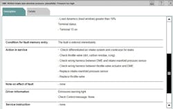
The factory ISTA scan tool description for a 28A0 code stated an interesting bit of information that had been overlooked,and is shown in Figure 14.
The statement underlined mentions that the fault is recognized when the monitored mass air flow rate rises above a limit value. This means that there is too much airflow being measured for the commanded throttle position. This statement effectively rules out any false air leaks into the intake system such as a leak in the intake manifold or any turbocharger plumbing. If there is too much airflow the mass airflow sensor has to be able to measure it so I am looking for how this could be possible. As you should suspect by now, I decide to perform a crankcase pressure test.
The pressure measures -7 inches of water (-17 millibar). This pressure is too high and indicates a leak into the crankcase. The arrow in Figure 15 points to a crankcase ventilation hose that connects to the turbocharger inlet pipe. This is downstream from the mass airflow sensor and airflow through this pipe can be measured by the MAF. The scan tool test plan for this code mentions to check for air leaks first and check the crankcase ventilation system next, see Figure 16.
After carefully removing the breather hose at the valve cover and plugging the hole with my thumb the crankcase pressure drops significantly. The pressure can be seen in Figure 17.
This hose connection is used to vent crankcase vapors into the incoming airstream when the engine is operating under boosted conditions. There should be no airflow through this tube at idle. A look at the crankcase ventilation diagram found in a BMW training book shows how the system operates under normal load and boost conditions (when pressure is present in the intake manifold, instead of vacuum). Item number 12 in the diagram is a non-return valve that opens during turbo boost operation. This is a normally closed valve but it is stuck open on this BMW.
The repair on this BMW was replacing the valve cover with a new part, the valve cover contains most of the components of the crankcase ventilation system. One last item to mention about this issue can be seen from the test plan information (Figure 19).
The bottom two items mention replacing parts; this is what will draw the attention of most technicians. The top item states to check for air leaks in the intake system and crankcase. If you do not have a means to test the crankcase for leaks, this step is most certainly overlooked or bypassed entirely.
I hope this discussion of crankcase pressure measuring helps you to diagnose some troublesome drive-ability issues and adds another test to your diagnostic toolbox.


