Editor's note: This article was originally published March 1, 2009. Some of the information may no longer be relevant, so please use it at your discretion.
What does an engine need to start? Air, fuel and spark, and it all must be correctly timed. Modern engines rely on signals from crank and cam sensors to determine when to fire spark and inject fuel. The ECM uses signal pulses from the crank position sensor (CKP) to calculate when a particular cylinder is approaching top dead center. The pulses from the cam position sensor (CMP) are used to decide whether it is on a compression or an exhaust stroke.
When either signal is lost, the ECM may shut down ignition, injection or both. Sensor failures are extremely common on certain makes. In the past, a failed sensor frequently meant a no-start or an engine that died "just like you turned off the key" going down the road. Today, many engines can limp home despite failure of a single sensor.
However, codes typically set and extended cranking may be required. The relationship between the two signals is as important as the signals themselves. Some DTCs are related to the loss of cam/crank signal correlation or synch. This is often an indication of an underlying mechanical problem that causes cam and crank pulses, while still arriving, to arrive in an unexpected order.
They can also be caused by factors interfering with the normal signal pattern — amplitudes out of spec or frequency variances, depending on the type of sensor. More common are the P0340 camshaft position sensor circuit malfunction and P0355 crankshaft position sensor circuit malfunction.
Using a digital multimeter (DMM), a quick check of sensor resistance can be made against manufacturers' specs. Visual inspection can reveal a physically damaged or oil-saturated sensor. Using the frequency setting on a DMM, it may be possible to detect the presence of an AC signal output while cranking, but a dual-trace oscilloscope remains the preferred tool for verifying signal integrity, amplitude, and CMP/CKP synchronization.
Sensors are constructed using a variety of technologies, including variable reluctance andhHall effect. Hall effect sensors typically produce a square wave, digital pattern, while magnetic or variable reluctance sensors produce more of a sine wave pattern. Shielded wiring is frequently used to maximize signal quality. Electrical interference from failed alternator diodes, noisy secondary ignition leads and even bad engine/transmission grounding have been known to interfere with CMP and CKP signal integrity.
Other problems that can cause issues with CMP/CKP signals include accumulation of magnetized debris on the sensor tip, stretched timing belts and chains, cracked flexplates, and wiring/connector problems. Excessive end play on crankshafts/camshafts can also cause variations in the signal.
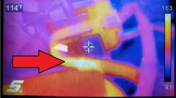
Some sensors are notorious for heat-related failures, dropping out only once an engine warms up. Both "tap testing" and applying a heat gun are ways techs sometimes confirm intermittently failing sensors.
Getting in Sync
Techs may need to compare side-by-side oscilloscope patterns of CMP/CKP signals to known good waveforms when diagnosing synch problems. Waveforms are increasingly available on technical information services and manufacturers' web sites, as well as a host of aftermarket sites. The timing relationship (synchronization) of the two signals will get altered if a timing belt skips teeth, a cam gear slips or a cam phaser misbehaves. Signal quality (amplitude and frequency) can be affected by cracked reluctors and missing reluctor teeth.
Engine and head parts swaps sometimes result in mismatched reluctors and ECMs. Software within an ECM expecting to see 37 crank pulses between CMP pulses that only gets 35 can't properly calculate when to fire spark. These and other mechanical problems all can result in a loss of synch because the pulses no longer arrive in the expected sequence, and with no synch, you usually get no spark.
The actual sync, or relationship between CKP pulses and CMP pulses, usually involves one or more distinct rising or falling edges occurring before another particular signal transition. Looking at a reference waveform, a tech typically can figure out what the key relationship is and compare it to the patterns he or she is seeing on a dual-trace oscilloscope.
CMP/CKP Synch status (yes/no) is displayed on many scan tools. However, it can't always be trusted nor do all vehicles have adequate reluctor resolution to detect a timing belt jumped only a single tooth or stretched. One or more reluctor teeth per cam gear teeth would be required to achieve that level of resolution, although by properly biasing the reluctor teeth relative to the cam, a belt slipped in a single direction may be detectable with fewer teeth.
Signals from the CMP and CKP are used for tasks other than just controlling spark and injection. VVT operation may be monitored. Tachometer information is normally derived from the incoming CKP pulses. RPM sensing may be used to disengage or disable the starter, preventing grinding, as well as to enable continued fuel pump operation after starting. Acceleration/deceleration of the rate of CKP pulses arriving at the ECM corresponding to cylinders firing is used by the ECM to detect a misfiring cylinder on many models. An expected acceleration simply doesn't occur when a cylinder misfires. After replacing any of the sensors or the PCM, a crankshaft variation re-learn is required on many vehicles before the misfire monitor will operate correctly.
Early systems sometimes incorrectly set misfire codes when vehicles were driven down rough roads. Today, crankshaft variation relearn procedures "calibrate" sensors to flywheel reluctor teeth to accommodate for normal manufacturing variances. Along with improved software, this minimizes this problem.
CMP and CKP signals keep track of the engine's timing, in essence, not only providing the ECM with an electronic "heartbeat" but also performing the equivalent of an "automotive EKG," detecting when the correct rhythm is lost.
Fortunately, ECMs are pretty good about setting codes when CMP/CKP problems exist. However, they don't always get them right. Sometimes they'll set a code for the unfailed, rather than the failed, sensor.
Essentially, the ECM is just counting pulses and comparing them to an expected pattern. If it sees more than "X" number of CKP pulses arrive before it sees a CMP pulse while cranking, it should set a code for a failed CMP sensor. If it sees CMP pulses along with other indications the engine is running, but no CKP pulses arriving for "X" number of seconds, it should set a code for a failed or intermittent CKP sensor. Inadequate size or shape of pulses caused by shorted or failing sensors can cause DTCs for Sensor Performance to set as well.
Summary
Understanding cam/crank sensor synch, waveforms and codes has become valuable information for today's techs. Techs will find there's no substitute for being able to use an oscilloscope when it comes to diagnosing problems related to CMP/CKP signals. Manufacturers have come up with endless variations on the number of "teeth" on crank and cam reluctors, and their timing relationship, types of sensors, signal levels, and so forth.
Comparing actual signal waveforms to reference waveforms is frequently required. Techs should check for TSBs (Technical Service Bulletins) and/or campaigns related to CMP/CKP sensor replacement, as well as those relating to actual testing of these components.
Wade Nelson is an electrical engineer who has worked for GM, Motorola and a mobility van conversion firm, and has taught automotive electronics at San Juan Community College. He has also written service and wrenched.