This article was originally published March 1, 2010. Some of the information may no longer be relevant, so please use it at your discretion.
Modern vehicles not only use more electronics, but those same electronics are more interlinked than ever before. Typically, every control module on the vehicle is linked to a network through one or more communication lines. This means one part of a system can have effects on a seemingly unrelated part somewhere else. Because vehicle systems are so interlinked, we need a new strategy to diagnose an old problem.
Parasitic load testing used to consist of removing the negative battery cable and inserting a test lamp in series with that cable to see if enough current flowed across the lamp to light the filament. If the filament did not illuminate to full brightness, it was okay to remove the lamp and wire your 10A-limited ammeter in series to measure the actual draw. Once a parasitic draw was seen, you pulled the fuses, components or relays until the offending current draw disappears.
This method no longer works because you have to disconnect the battery in order to install your test equipment. When you disconnect the battery on a modern vehicle, one or more modules or components that might have been awake and drawing current might be put to sleep, temporarily eliminating the very parasitic draw you were attempting to locate. Pulling individual fuses that feed one or more components has the same problem as disconnecting the battery, albeit not as globally.
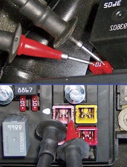
So how do we locate the offending circuit without powering down that same circuit using the older power disconnect test methods? We measure the voltage drop across each of the fuses. That's right, even a fuse has some resistance when heated due to current flow across it. This means the fuse that has current flowing will have a measurable voltage drop across it. Simply set your DMM to the millivolt scale and place the test leads across the fuse as shown in Figure 1.
How much of a voltage drop is too much? It depends on the physical size of the fuse, the fuse rating and, of course, the amount of current flowing across that fuse. More current creates more heat, which creates more resistance and a greater voltage drop.
A maxi fuse has a fatter current path, and so more current can flow at a lower voltage drop than that of a mini fuse. A lower fuse rating means the fuse element is thinner, which creates more of a voltage drop than the same type fuse of larger rating.
But there is no need to worry about exact numbers though; simply play "one of these things is not like the other." All fuses of the same type and rating will have the same voltage drop unless different amounts of current flow across them. More current equals a larger voltage drop.
In Figure 2, the 0.1mV top reading is from dead circuit protected by a 30A cartridge style fuse. The 0.7mV middle reading is from the same 30A cartridge fuse with 1A flowing across it. With 1A of current flow, the voltage drop is seven times larger. The 4.5mV bottom reading is from a 10-amp mini fuse with 650mA flowing across it.
This smaller mini fuse of lower rating and lower current flow suffers a much larger voltage drop than the 30A cartridge fuse. All the other 10A mini fuses on this same car read 0.2mV with no current flow.
The best way to locate a parasitic draw is to drive the vehicle and operate all of the options during this test drive. Then turn the key off and wait the manufacturer's recommended time for all the modules to go to sleep.
Do look up this test information, as many vehicles today can stay awake for about an hour or have modules turn back on after a period of time.
Some manufacturers recommend the use of a preinstalled battery cable parallel switch tool to negate the need to disconnect the battery after the test drive. I prefer to use an inductive current probe and digital multimeter (DMM) or scope to make more varied and targeted measurements. Use the current probe according to the method outlined in the October 2007 Scope & Scan column "Don't Blow Your Fuse" to find the exact offending circuit and component.
At times, you may have to keep the door of the vehicle open in order to gain access to an interior fuse panel for testing. This may keep many interior circuits live and drawing current.
Depending on the location of the door pin switches, either remove your door pin switches or move door strikers to their closed positions.
Jim Garrido of "Have Scanner Will Travel" is an on-site mobile diagnostics expert for hire. Jim services independent repair shops in central North Carolina. He also teaches diagnostic classes regionally for CARQUEST Technical Institute.


