Sometime at the beginning of the 2004 model year, Subaru re-designed this transmission again while maintaining the same clutch and brake application. It is called the 4EAT Phase 2 Version 2 and you cannot tell the difference by just looking at the transmission.
The only sure way of knowing is by dropping the pan and look at the valve body. There you can see a significant change. The whole entire valve body, filter configuration and solenoid arrangement are completely different when compared to Phase 2 Version 1. The case passage also changed to accommodate this new design.
By locating the part number for the filter used in this new set-up, we were able to identify the original vehicles that received this Phase 2 Version 2 transmission:
1. 2004 and Later Subaru Forester Turbo
2. 2005 and Later Subaru Forester Non-Turbo
3. 2005 and Later Subaru Impreza Non-Turbo
4. 2005 and Later Subaru Legacy/Outback
5. 2006 and Later Subaru Impreza Turbo
This complete electronic and hydraulic change took place so as to offer Tiptronic Shift Control. The new design allows the solenoids to have individual clutch control as seen in the hydraulic schematics shift from first to second gear.
If you look closely at these hydraulic schematics, you also will notice that each of the shift solenoids sends its control signal pressure to its respective control valve. The Low Clutch Duty Solenoid sends oil to the Low Clutch Control Valve; the 2-4 Brake Duty Solenoid sends oil to the 2-4 Brake Control Valve; and the High Clutch Duty Solenoid sends oil to the High Clutch Control Valve.
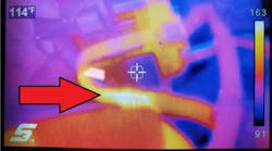
Pay Close AttentionThe concern here is that the solenoid signal pressure is supplied between the end plug and the valve. With the valve being pulsed on and off by the solenoid, the valve will tap the bore plug. Over time, the bore plug will rock in its bore wearing the outer edges. This will compromise its sealing capacity of the solenoid signal pressure. If enough can sneak past the bore plug the clutch control valve will not apply its clutch properly causing either a gear ratio error or a solenoid performance code or both.
A simple little leak in this area can be big trouble and easily overlooked. At the time of writing, these solenoids are not available separately. The entire valve body assembly will need to be purchased for approximately $725. So if you should encounter one of these units with solenoid performance codes, check these bore plugs first. As this becomes an issue, there will be aftermarket sources to replace these plugs.
In the meantime, carefully run a pipe cutting tool around the bore plug to give it a little flair. This will provide a slight interference fit in the bore will sufficiently seal the solenoid’s signal pressure. One note of caution here: Tap the bore plug in just enough to allow the retainer to drop into place. If you tap the plug far into the bore, it will affect the stroking of the valve and you will have a new problem on your hands.
Because I already mentioned that solenoids for this valve body are not available separately, you should know that one of these solenoids goes bad frequently. The connectors on the solenoids are either brown or black and then there is one that is green. This green connector solenoid is the Transfer Clutch Solenoid used to provide the AWD feature. This means there no longer is a transfer clutch solenoid assembly in the rear of the transmission. It is this green connector transfer clutch solenoid that fails frequently causing the same wheel hop complaint the previous version experiences.
However, to apply the transfer clutch, this solenoid has to be energized. It works opposite from the solenoid used in the Phase 2 Version 1 transmission. When the solenoid is off, the transfer clutch is off. When the solenoid is turned on, the transfer clutch applies. This also means you will NOT find an AWD fuse under the hood to diagnose your wheel hop complaint. While in turns this solenoid should be off. If it’s being energized during turns then there is an external problem. If it remains off, then internal issues are present.
Vehicle owners may have concerns with this transmission that cannot be fixed as Subaru explains in a bulletin they entitled, “Phase 2 4EAT Transmission Characteristics.” It reads as follows:
SOA and FHI have been investigating returned OEM transmissions for the last several years. We have been concentrating on units returned that were tested and found not to have any problem during the Dyno testing and disassembly inspection of the unit. Based on the paperwork comments, we have identified several different symptoms that would be considered normal operation for the unit. These characteristic symptoms will not be corrected by replacement of the unit or any components within the system.“Phase 2 4EAT transmissions have been used in Subaru vehicles since the 1999 Model Year. They can most readily be identified by the external ATF oil filter located on the driver's side of the transmission case. Be advised that H6 equipped vehicles use a remotely located ATF oil filter. This filter is located in the Left front fender well area.”
It is important to understand that many decisions are made in the designing of the transmission.
Items like fuel economy and emissions play a big part in the design. The design of the new 4EAT considerably increases the fuel economy and reduces the overall emissions of the vehicle. To accomplish this, the design incorporates fewer parts than its predecessor. This not only reduces the total friction, but also the overall weight of the unit. Because of this, the unit functions differently than the older 4EAT.
How to Address Problems
The purpose of this article is to make you aware of these characteristics, so when you receive a concern from a customer, it can be identified and explained to them quickly. Repairing of a vehicle starts with detailed questioning by the service advisor as to how, when, and where the condition occurs. Duplicating the how, when and where by the technician should enable the concern to be identified.
If the concern is similar to one of those listed below, it should be explained to the customer that it is a normal operating characteristic of this model and not an indication of any decreased reliability or future trouble. No repairs should be made to the vehicle. If you are unsure, we recommend you road test a similar vehicle. If both vehicles are similar, chances are it is a characteristic of the unit.
1. Delayed Engagement or Judder felt when shifting into Reverse or Drive.
Symptom: When the driver shifts the select lever into reverse or drive and applies the accelerator too quickly delayed movement or a judder can be felt.
Recommendation: To determine there is an internal problem with the unit, perform a TIME LAG TEST as outlined in the appropriate Service Manual for the vehicle. If the average is less than 1.5 seconds the unit is operating normally. If it is more than 1.5 seconds then an internal problem exists and repair/replacement should be preformed. Explain to the customer the mechanism and function of the system and that it is not a defect in the unit. Also, recommend that the customer wait a second or two before applying the accelerator pedal.Mechanism: It takes approximately 1.5 seconds to engage the internal clutch(s) after the select lever gear is chosen. If engine torque is increased before the clutch is fully engaged, the clutch will slip and make the judder feeling.
2. Shock felt during light acceleration with the Lockup clutch applied.
Symptom: When the driver tries to lightly accelerate the vehicle, when driving at a constant speed in 4th gear and the Lockup clutch is engaged, they may feel a slight shock through the body of the vehicle. Some customers may compare it to a manual transmission vehicle.
Mechanism: When the accelerator is pressed lightly (approximately 20 percent or less), the lockup clutch is not released. This causes a direct coupling between the engine and the drive train of the vehicle. The slight shock is from the small clearances in the drive train gears, axle splines, etc. If the lockup clutch is not applied then, the fluid coupling in the torque converter absorbs the shock. Under certain conditions, this same shock can also be felt when activating the cruise control.
Recommendation: Explain to the customer what they are feeling is a normal operation. Basically, the lockup clutch is kept on as much as possible to increase fuel economy of the vehicle. Increasing the engine load (driving on hills or pushing the accelerator more) will disengage the lockup clutch sooner. We recommend you try duplicating this during some of your road testing (PDI) so you are familiar with the sensation. To do this, drive at a constant speed around 40 mph.
Confirm that the lockup clutch is applied (use Select Monitor) and accelerate using light throttle. You will feel a slight shock throughout the body of the vehicle.
3. Click noise when transmission shifts from 2nd to 3rd.
Symptom: When the transmission upshifts from 2nd to 3rd gear under light acceleration, a click can be heard from under the vehicle. Most customers will only notice this noise when they have the driver's window opened and are driving close to some structure that will reflect the noise back into the vehicle.
Mechanism: The noise is created when the 2-4 brake is released during the 2nd to 3rd gear upshift. At this time, the clutch steel plates that are located into groves on the internal wall of transmission case shift creating the metallic click noise.
4. 2nd to 3rd shift flare after vehicle is parked.
Symptom: After a vehicle is parked and it sits typically overnight, when it is started and the transmission upshifts into 3rd gear for the first time, the rpms might flare slightly. This can be an intermittent condition depending on how the vehicle is positioned when parked, temperature of the transmission when parked, and ambient temperature.
Recommendation: Explain to the customer how and why they are experiencing this symptom. Also, make sure they understand it is not causing any damage or excessive wear to their transmission or vehicle.Mechanism: The shift flare occurs because the hydraulic circuit for high clutch in the transmission occasionally drains. When the transmission upshifts for the first time into 3rd gear, the hydraulic circuit must fill before it will apply the high clutch. The time needed to fill the circuit slightly delays the applying of the clutch causing the rpms to rise slightly. The transmission will function normally for the rest of the driving cycle.
5. Transmission delays downshifting during low to middle speed acceleration.
Symptom: The driver wants to accelerate quickly and starts applying the throttle, but the transmission will not downshift to a lower gear ratio until almost full throttle.
Mechanism: Basically, the logic (normal shift map) that controls gear selection is trying to keep the transmission in the highest gear possible for fuel economy. Subaru vehicles utilize a microcomputer (TCM) for accurate control of the gearshift timing, engine braking, lock-up clutch operation and other functions. It directly corresponds to throttle opening, vehicle speed, engine speed, and gear selector position. Various sensors and switches located on the vehicle feed information to the TCM.
The TCM will make calculations based on all these inputs. The throttle position sensor provides electrical signals corresponding to the accelerator pedal position. The TCM not only can calculate how far the accelerator pedal has been depressed, but how fast it was depressed. In other words, the system detects the driver’s direct input from the accelerator pedal and will shift the transmission accordingly. Depending on the vehicle speed, if the accelerator pedal is slowly pushed down evenly to the floor, the TCM may not downshift the transmission.
If, however, you quickly depress the accelerator pedal to the floor, it certainly will downshift into whatever the TCM determines will give the driver the best gear range for power and acceleration. This is a direct driver input and depending how far and fast the accelerator pedal is depressed will determine the vehicle power and acceleration. This gives the driver some ability to operate their vehicle based on power or economy. Another item to consider is the internal operation of the transmission. In most cases, the TCM must turn off one clutch and apply another to change gears. If a clutch is turned on or off too soon it would cause a harsh shift. It also could cause premature wearing of the clutches. The logic was chosen to provide a balance of shift feel and wear characteristics. Fluid temperature is also a consideration. Cooler thicker fluid takes longer to move though a given passage than warmer thinner fluid.
6. High Frequency noise driving at 65 to 70 mph.
Symptom: The driver hears a high frequency noise (whine) between 65 to 70 mph during a steady throttle or coasting. Noise can only be heard driving on a smooth flat road with the windows up and radio off.
Mechanism: The noise is being generated by the reduction gear teeth in the rear of the transmission. The noise will only be heard on slight acceleration or coasting not both. It is not an indication of an internal problem and will not create any trouble.
Subscribe to Motor Age and receive articles like this every month…absolutely free. Click here