GM’s 4L60-E, 4-speed longitudinally mounted transmission with a strength rating of 60, was designated with an E to indicate that it is electronically controlled. However, since its inception in 1993, this transmission has received an endless list of changes and updates rendering the meaning of E to double as evolution. A basic overview of the changes made to the electronics alone will prove my case.
From 1993 to 1994 the transmission was originally fitted with a Pressure Control Solenoid, two Shift Solenoids (A and B), an on/off-type TCC Solenoid, a PWM 3-2 Downshift Solenoid, a Pressure Switch Manifold and a Vehicle Speed Sensor.
In 1995, a PWM TCC solenoid was added to the system to work in conjunction with the on/off solenoid. The on/off solenoid turned the converter clutch on and off while the PWM solenoid controlled the rate in which the clutch applied and released. Some models received an external two-harness connector Park/Neutral Position switch on the manual arm shaft.
In 1996, the PWM 3-2 Downshift Solenoid was then changed to be an on/off-type solenoid. This configuration of electronics remained in play until 2005 with one exception. The two-harness connector Park/Neutral Position switch was redesigned in 2000 and is referred to as the PNBU switch. In 2004, this switch was redesigned again and has only one harness connector.
In 1997, the Electronically Controlled Capacity (Converter) Clutch (EC3) strategy was introduced in W body 3.4L passenger cars and then used in all models in 1998. EC3 is a slip-controlled converter clutch-apply strategy as early as second gear to a rare full apply under specific highway cruise conditions. This continuous low rpm converter clutch slip still improves fuel economy while further enhancing drivability by reducing driveline torsional disturbances.
As a result of computers being redesigned and/or programmed to accommodate these many changes, a variety of issues can come up when the wrong year transmission and/or torque converter is installed into a vehicle. One such example is when the first design 1993- or ’94-type transmission is used in a 1995 vehicle. This would cause an electrical fault code for a PWM TCC. Or, use this same early design transmission in a 1996 vehicle, and you will have codes for both the PWM TCC solenoid and the 3-2 downshift solenoid.
In 2006, a very significant change took place. An internal Input Speed Sensor (ISS) was added to the system. This allowed the computer to monitor the shifts and gear ratio for enhanced line pressure control. Aside from a new input to the computer and its related program, changes also were made to the internal wiring harness and pass through connector.
In 2009, two more significant changes occurred. The 3-2 Downshift solenoid was eliminated as a result of the enhanced line pressure control the ISS strategy provided. And the external PNBU/NSBU was replaced with and Internal Mode Switch, which also eliminated the internal pressure switch manifold.
The many noteworthy changes to the 4L60-E’s electrical system alone certainly qualifies the E to mean evolution, and we have yet to mention any constructional changes.
Both the case and internal parts received various changes over the years. In fact, there has been such a number of them it’s not possible to cover them in one article.
Some of these changes were phased in over a period of time rather than being immediately implemented. This widens the margin of mismatching parts during a rebuild as some of these changes were very subtle. An example of this was when they added an internal input speed sensor to the 4L60-E in 2005. The sensor is mounted on the pump, which reads rotor teeth that was added to the input (turbine) shaft. To accomplish this task, dimensional and hydraulic changes needed to take place with both the pump and input shaft. These dimensional changes accommodated the added rotor teeth on the input shaft, the repositioning of the sealing rings on the input shaft, the added sensor on the pump, its harness and connector so it can plug into the already existing harness which too had to change.
The implementation began in February with a new design TCC valve in the pump. This new design utilizes only one spring as opposed to the previous two-spring design. In March, a more compact boost valve and sleeve was designed to shorten up the length of the Pressure Regulator Valve line up in the pump. This was done to make room for the ISS harness connector.
In July the pump casting was modified to accept this new harness. No holes were yet bored for the sensor itself or for the sensor’s mounting hole. A change to the hydraulic circuit in the pump was also made. Part of this change included a modified stator shaft and stator shaft sleeve. This was done to accommodate changes made to the input shaft. To add rotor teeth to the shaft to be used to excite the speed sensor, the sealing rings on the shaft had to move. This is why hydraulic changes to the pump needed to be made as well as repositioning the stator sleeve.
During model year 2006, the full implantation took place. However, there are some models that did not receive the ISS. In these cases there is a plug bolted down into the sensor hole. If this is left out, a loss of converter charge pressure will occur resulting in a no move complaint.
Some of the mismatches that easily can occur are to use an input shaft that can dimensionally fit into a system that uses the ISS sensor in the pump yet the rotor teeth is not on the shaft. Codes P0716 or P0717 will be stored, which could cause TCC slip and gear ratio calculation errors.
If dimensionally different pump covers and input shafts are mismatched, severe friction and geartrain damage will occur in a short period of time. To help prevent making these errors in parts, look for a newsletter this month called “Pump and Input Shaft Usage.” This bulletin will identify the progressive changes that were implemented to assist you in getting the parts right.
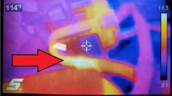
Some of these 4L60-E ISS applications use a separate TCM instead of being integrated into the PCM. These TCM’s have been known to give problems due to its design. Most recently, Elio JR. from WiWi’s Transmission in Miami called me with a 2010 Chevy Truck Express 1500 RWD V6-4.3L using a 4L65-E transmission. It had a No/Low Input/Turbine Speed Sensor Signal code P0717. He had already diagnosed it down to a defective TCM and invited me over to take a look at it.
When I arrived, he had the TCM on the bench. This little guy is attached to the right inner fender between the battery and the blower motor. We flipped it over and took the back off. In doing so, we saw these very thin wires (.010-inch) being used to complete the circuit from the connector terminals to the circuit board. Upon a very close look, we saw a broken wire going to terminal 45. Terminal 45 happens to be the low side of the ISS and the reason this hall affect sensor stopped providing a speed signal through terminal 3.
The TCM lists for $146.48 and NETs for $109.86 with a core charge of $25. It cost an additional $150 to program the TCM. Throw some labor on top of that and this little wire cost the owner close to $500. But if you are good at soldering, this could be an easy in-house repair.
With the TCM being next to the battery, there is another issue with the TCM of which you will want to be aware. There has been times where the TCM is accidently shorted to battery voltage. In fact this has occurred enough times that even GM has issued a bulletin regarding this dilemma (05-07-30-016C). In their bulletin it states: “It has been found that if the positive battery jump start post/terminal cover is removed and/or missing, and the TCM comes in contact with the positive battery jump start post/terminal during diagnosis and/or service, the TCM WILL BE DAMAGED and require replacement.”
Many thanks to Elio for inviting me over to his shop and for paying the TCM core charge so I could share this information with you.
Subscribe to Motor Age and receive articles like this every month…absolutely free. Click here