As a mobile diagnostic tech, I receive numerous calls from many different shops asking me to program a module or diagnose a problem vehicle that's in their shop. Many times the information I'm given over the phone isn't quite the complete story. In this particular instance, a tech called to tell me they had a 2012 Mitsubishi that had an Antilock Braking System (ABS) light illuminated on the dash and they couldn’t seem to find the problem. I arrived at the shop thinking that the vehicle in question was a car, but it turned out to be a medium duty truck, 2012 Mitsubishi Fuso FE160!
Like This Article?
Check out related training at
Most car and light duty shops around my area are not geared up and properly tooled to
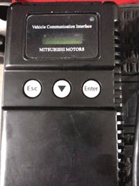
work on vehicles like this. As a mobile tech, I have to be able to cover just about every vehicle on the road. Not being able to service a vehicle is out of the question. When it comes to scanning these vehicles, they can be a little dicey, as most scan tools won’t communicate with these trucks due to the communication network protocol they use. You might get lucky communicating with it using a Global OBDII scan tool, but the information you will see might not be accurate or there is just not a lot of it. The tool of choice on these vehicles is the factory Mitsubishi scan tool, called the Multi-Use Tester (MUT) III. Because this is an ABS problem, I hooked up my tool to the Diagnostic Link Connector (DLC) and tried to communicate with the vehicle.
Talk To Me
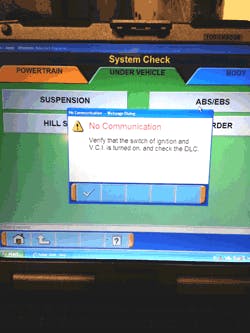
OK, that’s strange; there isn't any communication with the ABS module. Is that why the ABS light is on? I wanted to make sure that the tool was working, so I tried communicating with the Engine Control Module (ECM), which it did. Before I located the ABS control module on this vehicle to check its powers and grounds, I wanted to make sure that the scan tool was at least attempting to talk to thiscontrol module.
I installed a DLC breakout box between the connector and the scan tool. This is a great tool to use to check the circuits at the DLC connector for proper power and grounds. On this vehicle, pin 16 is power and pins 4 and 5 are grounds just like the cars
and light duty trucks on which you normally work. Those circuits checked out just fine. The communication lines on this vehicle are pin 7 and pin 13. As I tried to communicate with the scan tool, the pin 7 light illuminated on the breakout box. That told me that the scan tool was at least making an attempt to communicate with the ABS module. I also verified that I was receiving a signal of about 12 volts with my Digital Volt-Ohm Meter (DVOM). The next step I took was to locate the control module itself and with the help of a wiring schematic, I checked the powers and grounds to the module. Those, too, checked out to be working properly.
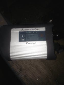
Why can't I communicate with this module? By all accounts I should be talking to it based on the testing I have done so far. My next step was to use one of the most powerful tools I have in my arsenal: networking. I contacted a friend at the Mitsubishi dealer and asked him about this problem. He told me that in 2011/2012, Mitsubishi started using a tool called the SD Connect, the same tool used on the Mercedes Benz vehicles. I plugged my SD Connect VCI (Vehicle Communications Interface) and finally was able to connect with the elusive ABS module.
Now That We’re In
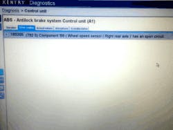
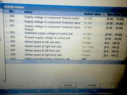
The generated code was for a right rear wheel speed sensor open circuit. When a sensor circuit code is reporting “open,” there could be a couple of causes for the problem. The sensor could be disconnected, the wires from the control module to the sensor connector could be open or broken or the sensor itself could be internally open. I’ve already done a lot of testing so far just to see why I wasn't communicating with the ABS system, now it's time to get to some serious testing and find out just what is causing this truck to turn the ABS light on. I did a quick scan of the ABS data just to make sure everything looks ok, but I clearly can see a problem.
I go to my information system and pull up a wiring diagram of the ABS system for this vehicle. At the ABS module, I remove connector AH26A from the module and hook one of my test leads from my DVOM to terminal 17 of the connector. At the other end, I disconnect connector AB14B (which is the connector going to the right rear wheel speed sensor) and I connect the other lead connector terminal 1. I set my meter to the ohms setting and read my results. My meter read 0.01 ohms of resistance. I at least know that the path between the two connectors is complete.
That being said, I like to do a more thorough circuit integrity check. I take a headlight bulb and wire it in series so I can apply the headlight to the circuit being tested. The headlight now becomes the load in the circuit. If the headlight shines bright, it is a good indication that the wiring in this circuit is in good condition. If the headlight is dim, then that would tell you that there is a potential problem in that circuit. An ohms test might not pick up the problem on the circuit, but this test surely will.
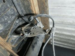
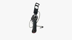
Next up would be back by the wheel area itself. With the sensor disconnected, a visual inspection into the cavities of the connector is important as this is where a lot of road salt, grit and dirt build up could accumulate which can bring on corrosion. Next, I removed the sensor from the backing plate. With the sensor removed, I found a lot of particles on the sensor tip which is magnetic but not enough to create a potential problem reading the ABS tone ring. I used a video scope and pointed the scope inside the hole where the sensor usually resides so I could get a good look at the toner ring. I could clearly see the teeth on the ring. I had a technician in the shop raise the rear of the truck off the ground and spin the wheel while I looked at the ring. I did not see any missing teeth, a loose wheel or any wobble in the ring as the wheel was being spun.
When I performed the first test on the type 1 sensor, I hooked up my meter to both terminals on the sensor harness and set my ohm meter to auto range. I came up with a reading of 2.7K ohms. That reading is way out of spec. As I was testing this sensor, I went along the harness and wiggled the wires and watched my meter. The readings changed a little bit but they never went in spec. Now I can say its time for a new sensor but being the perfectionist that I am sometimes I still want to perform the second test as well.
I hooked my meter up between one terminal and the sensor housing. Terminal 1 read 1,100K ohms, which is, in fact, in spec. Next I hooked to terminal 2 and the sensor housing and my reading was 130,000 ohms. With that reading, I knew that this sensor was, in fact, bad. Now I am satisfied with my diagnosis and any and all doubts are now gone.
I reinstalled the connectors to the ABS control module and had the shop order a new sensor and install it. I came back to the shop the next day and was able to clear the diagnostic trouble code from the system. The light is off and the customer and shop owner are happy.

