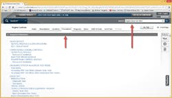
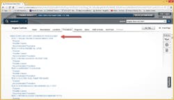
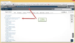
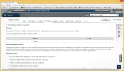
In February 2014’s Motor Age (also dedicated to diesels), I did an article on the analysis of hard start/no start concerns on the 7.3/6.0L PowerStroke engines. In that article, I only got through Step 1 of the 10-, 11-, 12-step procedure sheets that Ford required its technicians to fill out for trucks that were under warranty. The 7.3L had a 10-step process and the early 6.0L had an 11-step process, which was updated to a 12-step procedure.
Like This Article?
Check out related training at
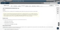
Ford also had a similar procedure sheet for these engines when they had performance concerns, and the technicians had to fill them in for warranty as well. These sheets worked well to find concerns in a timely manner. Experienced technicians could sometimes skip steps or jump to a certain step based on product knowledge and experience, but even they typically followed the procedure as each test step builds on the last. Jumping too far ahead might find the concern, but that is luck as opposed to skill.
What do I mean by that? The idea behind these charts is a logical test procedure that should find the concern in a timely fashion. It also makes sure that you don’t test something that appears bad because of another failure that you missed.
The idea behind this system is that you keep going until you find the concern and fix it. Also, accessing Ford service information is important. Each one of the following test steps has detailed procedures and specifications in the service manual.
Step One – Visual Inspection
In the last article I did, this is all the farther I got, and you may wish to retrieve and review that article. Make sure the engine is mechanically sound: the batteries, cables, starter and alternator are working correctly. If the vehicle is a true no start, then at least make sure the batteries and cables are good.
Step Two – Check Oil
The 7.3/6.0 PowerStroke uses a HEUI (Hydraulic Electric Unit Injection) injection system. The injectors use engine oil to operate, and bad oil equals bad operation.
We all know that the wrong viscosity oil can cause cold weather cranking concerns, and that doesn’t change just because you have a diesel. In fact, diesels are even more susceptible to this than gas engines. I’ve known many Ford diesel technicians who change oil as part of their analysis process. You might even need to consider having an oil analysis done.
Viscosity, contamination and level all are important. When I was with Ford, I took a 2002 Excursion with a 7.3 to an offsite training session. The vehicle developed an oil leak and lost two quarts before I knew it had a leak. I figured it out as the truck started doing a buck-jerk at low speed cruise and took longer to start. I checked the oil and found it was down just two quarts. That was enough to begin to cause concerns. The 6.0 has a different oiling system and is not as susceptible to low oil levels causing running concerns like the 7.3 but still will have similar low/contaminated oil issues.
Step Three – Intake and Exhaust Restrictions
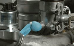
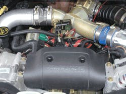
The 7.3 engines have an exhaust backpressure control on the turbo. This system is designed to close the exhaust outlet down to keep as much warm exhaust in the engine during warmup and extended idle during cold weather conditions. This is a flap that is opened and closed by the PCM directing oil pressure to one side of a piston. If this flap is stuck closed or if the flap has broken off the shaft so it opens and closes by itself, you will have an engine that can’t breathe well enough to start easily. It will also have very poor performance.
The 6.0 engines have a variable rate turbo and when it malfunctions the concern typically is performance related, but can also effect crank times.
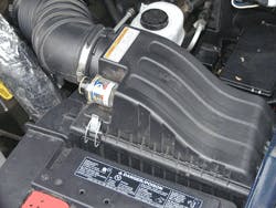
Most of these engines have filter minders on the air box, which is a way to check for intake restrictions.
Because of the age of these trucks you may also be dealing with a Charge Air Cooler concern. Any turbo system is susceptible to some oil seepage as well as blow by gases. This oil mist can condense out in the CAC and over time begin to plug off the passages. Poorly filtered air can allow dirt to enter and combine with any oil that may be in that cooler and cause blockage.
When was the fuel filter replaced? Is there water in the fuel? Of course the real kicker: Is it out of fuel? Yes this actually happens more often than you would like to think.
Step four can often be done in combination with the steps five and six, fuel system delivery on the 6.0L.
Step Five on the 7.3L
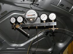
Testing the fuel system on each engine is looking for the same things. It is the same in that we are looking for a specific pressure at the injectors (as close as we can get a gauge) and we back track through the system to find our concern.
For those of you who use a scope as a primary analysis tool, you might wish to do some quick tests on the electrical side of the system. Using a low amp probe, check to see if the pump is powered up by the PCM. What is the current draw and pump rpm? If these are suspicious, check for power and ground at the pump.
Tech Tip: These testing procedures might drain even good batteries. Make sure that you use a quality battery charger that can maintain at least 12.5 volts during testing and will never exceed 15 volts.
You should have confirmed that the batteries are good and if not replaced them back in step one. If you could not start the truck, you don’t know whether the charging system works, but you will have confirmed the engine is mechanically sound so you can justify the new batteries. Yes, bad batteries will cause hard start, no start concerns, even with jumpers or a charger.
On the 6.0L you can check at the filter housing. If the pressure is low here you are asked to check pressure into the filter housing on each engine, then pressure at the pump outlet and finally on the suction side of the pump.
The 6.0L circulates fuel between the filter housing on the top of the engine and the Fuel Pump Module assembly located on the frameStep 6 – 6.0L Fuel System Inlet Restriction
Running these tests also is where the extra step comes from in the procedure sheet on the 6.0L engine. On the 6.0L, the fuel pump suction test for tank inlet restrictions is step six, while on the 7.3L it is part of step five.
Next Steps
For this part, steps six, seven and eight are for the 7.3L KOEO continuous injector self-test and KOEO injector test. Also, steps seven, eight and nine are for the 6.0L KOEO continuous injector self-test and KOEO injector test.
The 7.3L has two modules that control the injection system, the PCM and the IDM. Communication with these modules is very limited with the IDM and more robust with the PCM. Because of this, checking for codes is done out of order from what we have done on Fords for many years. You’re probably in the habit of checking continuous first and clearing and then doing KOEO and KOER. On the 7.3L, if you do that, you will clear any IDM codes without ever seeing them.
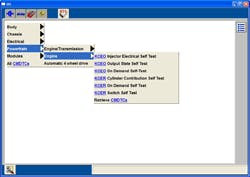
IDM codes are read during KOEO but are cleared in continuous codes. So you do a KOEO (step five) and record all codes. Then without clearing the codes go right into checking Continuous Memory Codes (step six). Record those and now clear codes.
Run the KOEO Injector buzz test and see if any IDM codes appear. If they do, these are hard faults. If there were IDM codes before and none come back, then they were memory codes. Repair and then clear codes before moving on.
RPM checks to see if the crank sensor, but wait as there is only a cam sensor on this, the 7.3L engine. This test is to see if the PCM sees the cam sensor and that it is actually turning at a 100 rpm minimum cranking speed.
Injection Control Pressure (ICP) during normal operation means this PID will vary between 750 and 3500 psi. The default is 500, and if it never goes higher, then the PCM is not controlling injection pressure or there is a massive oil leak keeping pressure from being able to be built up.
Tech Tip: Monitor the IPR PID, Injection Pressure Regulator as well. This is the PCM command to the High Pressure Oil system. The default value is 14 percent, and if it does not change, then the ICP won’t either. The maximum value you will see on this PID is 65 percent, which is calling for maximum oil pressure. The PCM must see the rpm signal before it will control this system.
For FUEL_PW Fuel Pulse Width, injector on time, both of these engines use a variable pressure fixed pulse width fuel control. Therefore the on time will usually by approximately 3 milliseconds except during crank, acceleration and deceleration. The amount of fuel sprayed into the engine is controlled by varying the oil pressure to the injector. If the value does not change, then the PCM is not controlling the system.
The 6.0L has additional PIDs to monitor during what is step 10 for this engine. They are B+, FICMPWR, FICMVPWR, FICMMPWER, RPM, ICP_DES, ICP, IPR, ICP, FUEL_PW and FICMSYNC.
B+, FICMPWR, FICMVPWR are checks to see that the modules are getting power, like the 7.3 8.0v minimum, more is better.
FICMMPWR is the available voltage to operate the HEUI injectors. These run at a voltage less than the 7.3L, but still enough to be cautious when electrically testing injectors.
FICMSYNC the 6.0L has a cam and crank sensor. The 7.3: only had a cam sensor. On the 6.0L, the PCM is looking for both signals and comparing when they occur. If the PCM loses either signal the engine may stall if running and may also be a no start.
Case in Point
A 2007 F250 was hard starting and stalling at low speeds but would run well at higher rpm. During certain crank and idle conditions the FICMSYNC PID would toggle between yes and no. During yes, the engine would start and run.
This engine uses a variable reluctance sensor for CMP and CKP. If these sensors do not create enough amplitude the signal is not recognized by the PCM. In this case, the CKP sensor signal was dropping below threshold at low rpm. The fix? Clean the mounting for the sensor. Rust had built up under the sensor and moved it away from the crankshaft increasing the air gap and causing the signal to drop out at low rpm.
When you pull up these sheets through Ford’s website or get the information from one of the other data suppliers you will note that the number of PIDs on this list is different from year to year. As the modules in the truck became more robust and scan tool software changed, more PIDs are available to us.
Step 10 (7.3L) Step 11 (6.0L) – Check Glow Plug Operation
The early 7.3L engines had a relay on the engine that looked like the Ford starter relays of days gone by to control the glow plugs, certain late model 7.3L and the 6.0L engines use a module. Glow plug on time is determined by the PCM and is based on engine oil temperature, ambient temperature and altitude. Most of the time, the early 7.3L systems turned on if conditions were correct and then cycled and turned off until the next key on.
Ford suggests various tests for this system. Some of them are of little value such as a resistance test on the relay contacts or circuits. Always test these circuits under load and voltage drop them, and use an inductive ammeter to check for current draw.
Tech Tip: When you test these components, be aware that glow plugs are easy to damage by leaving them on too long. Set up and perform tests quickly so that you do not damage good plugs.
Tech Tip: At the beginning of this article we discussed confirming that the electrical system was good. Electrical components cannot work correctly unless all power and ground connections are clean, tested, and known to be working without excessive resistance.
Step 12 (6.0L only) – Combustion Gas in the Fuel Rail
This last test is checking for leaking gaskets allowing combustion gasses into the fuel rail. The test first checks to see if there is a leak. If there is you are then directed on how to determine cylinder head and then actual cylinder(s) that are at fault.
As you gain experience on these engines, you might be able to skip to certain tests or do several at once. This overview of the process is designed to assist you in learning how to effectively work on these engines and becoming the go-to tech for PowerStroke diesels in your shop and town.

