Vehicles that roll into your service bay today have different engine configurations and operating characteristics and are significantly different than the vehicles that we took care of even 10 years ago. I’m sure you are aware that, in this industry, technology changes in the blink of an eye. The challenges faced by the OEMs in meeting ever-demanding CAFE standards means increasingly efficient (and sometimes complex) new engine designs.
In this article, we will cover some of the mechanical characteristics of how the Variable Valve Timing (VVT) engine works, what to inspect and look for and how to make your diagnosis of these engines a little easier.
Timing?
In an engine, timing is everything. All the elements (compression, ignition, fuel) have to occur in the right amount and at the right time in order for the engine to run even close to right. The problem is that the timing of these events is affected by the speed of the engine. What is right at idle won't work at all at cruise speeds. For years, the moment of ignition was the only factor that engineers could alter — first, by mechanical means and then later by computer. That's the idea of "timing" that many of us grew up on.
The computer was a neat addition to engine management. Not only did it allow engineers to more precisely control ignition, it also opened the door to conrolling the fuel event's timing. Still, there were gains to be made.
To truly gain ground in engine efficiency, the timing of the valve events needed to be altered as well.
Variable valve timing is the process of altering the timing of a valve lift event, and is used to improve performance, fuel economy and emissions. Common designs use a variable cam timing system that adjusts the camshaft to crankshaft timing, which is advanced at lower RPMs and retarded at higher RPMs, and effectively alters when the valves open and close. The timing is controlled by oil entering a passage and into a component called a camshaft actuator. A valve located on the block controls the actuator. When engine RPM increases, so does oil pressure. As oil pressure increases, the oil enters the camshaft actuator and forces the actuator to move off its position just a little bit. When that happens, the camshaft timing is altered.
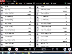
Here is a scantool shot of the fuel trims. Notice the difference in the bank 1 to bank 2 LTFT. Bank 1 LTFT is showing a rich condition.
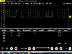
On this scope capture you can clearly see that the timing is off. Channel 1 is the camshaft sensor and channel 2 is the crankshaft sensor.
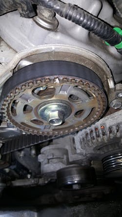
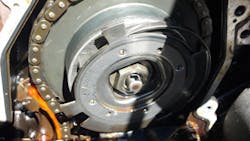
Here is the camshaft gear on bank 2. The timing marks are correctly aligned.
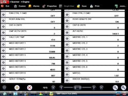
Here is a scantool screen capture of the multiple cylinder misfire history. This is why the PCM flagged the code P0300.
When an engine is at TDC or top dead center, that means the number 1 cylinder is at the top of the compression stroke and the intake and exhaust valves are in the closed position. This is for all combustion engines. This is your base starting point in your diagnosis as well.
Oil is a key component for proper operation and longevity of the VVT system. Many of these designs are controlled by oil pressure. The use of the incorrect oil can cause these systems to malfunction. Lack of maintenance can allow sludge build up in the VVT components (solenoids and actuators) and that will prevent them from doing their job. Failures related to proper lubrication and viscosity are the most common ones you will face.
Troubleshooting VVT — An example
When starting your diagnosis on one of these engines, it’s important to determine if this VVT issue is related to a fault internally or externally. What I mean by that is with an internal fault you must determine if the actuator sticking, lifters are failing or some other mechanical or even an electrical fault is causing the problem. On an external fault you could have a timing belt that is off a tooth due to improper belt installation or the belt is just plain worn out. It could be that the key way on either the camshaft or crankshaft is loose, worn out or broken. Most modern engines today will set a code or codes in the Engine Control Module (ECM) that will lead you in a good direction. Hook your scan tool up and look at your engine data, especially the camshaft data or timing data Parameter Identifiers (PIDs). You can gain a lot of knowledge about what the engine is doing or not doing.
With the scan tool hooked up and looking at some of the data PIDs we can see that there is a history of a misfiring engine. Looking at our scan tool screen shot, we can see that all cylinders are showing numerous misfires. On this engine, the cylinders run one, three and five for bank one and two; four and six for bank two. It appears that cylinder No. 2 seems to be the biggest culprit. Let’s not focus on a specific cylinder or cylinders for a misfire problem yet. Let’s look at some of the other data we’ve gathered. I want to mention here that this vehicle runs relatively well without any real engine roughness. What caught my eye was the long-term fuel trim numbers. Look at the scan tool screen shot that was taken here. Do you notice a difference between cylinder banks? Bank No. 1 is running a fuel correction of -14 percent compared to cylinder bank No. 2. Remember the only code was a P0300. There isn’t any air/fuel-related codes stored as the fuel trim isn’t excessive enough to set those codes.
Let's analyze what we’ve got so far. We have multiple cylinder misfires and a fuel trim reading from bank to bank that’s not correct. Sure, we could go after some more data like oxygen sensors or some of the other input sensors, but let’s look at what we have here first. The crankshaft sensor (CKP) tells the ECM what position the crankshaft is in. The camshaft position (CMP) sensor input is used to detect an engine misfire. The ECM also uses the CMP sensor signal as an input for modifying the fuel injection timing and for modifying the ignition timing. Based on the fact that the camshaft sensor is wh at monitors the misfires and we have multiple cylinder misfires, let’s actually look at what the camshaft sensor is seeing.
Here is a scan tool screen capture of the multiple cylinder misfire history. This is why the PCM flagged the code P0300.
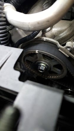
Here is the camshaft gear on bank 1. The timing marks are misaligned. This is the negative fuel trim reading on bank 1.
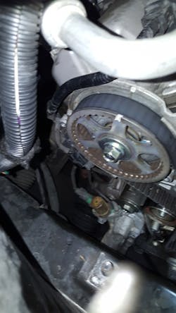
Here is the camshaft gear on bank 1 after the timing belt was realigned.
To do this I hooked up my scope and set channel one to my camshaft sensor signal circuit located on the left cylinder bank. I set my scope’s channel two to the crankshaft position sensor signal circuit. After starting the vehicle and getting my scope settings correct I could see right away that cam timing on this engine was a problem. What’s nice about using a lab scope is that I didn’t even have to pull anything apart to see this! Removing the belt covers revealed what the scope captures led me to expect — the timing belt was out of time.
The camshaft actuator solenoid on a 2013 Chevrolet Cruze
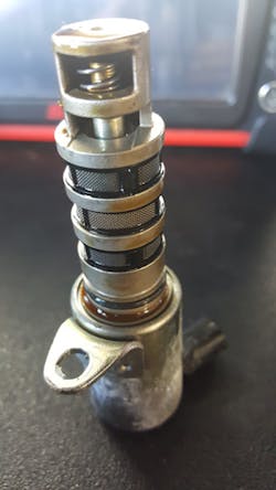
This is a camshaft actuator that failed. Notice the spring that came apart. Lack of oil pressure is what caused this failure. This is not off of our Chevrolet Cruze but the fundamental characteristics are the same.
With our first vehicle, I explained the importance of valve timing and the effects it can have on your diagnosis. The second vehicle explained the effects that a lack of good oil quality, quantity and maintenance can have on a modern engine of today.
When working on an engine with a VVT system, it’s very critical to take the time and gather all the facts. Understand how the system