Seemingly simple issues such as power windows that do not work, a no crank no start condition or even erratic operation of multiple systems can be due to a network fault. In addition, a network issue is often a surprise to the technician due to the fact that the customer’s complaint may seem to have no correlation to the actual fault. Given these statements, let us explore network diagnosis.
Networks can fail in multiple ways. The diagnostic approach we choose depends on the type of communication failure we are presented with. Some examples of failures include one module does not communicate, some modules do not communicate, all modules do not communicate or modules set “U” codes for network communication. Of course, there are additional failures, but these are the most common. Each of these failures may require a different approach. However, there is a four-step plan of attack that can point us in the correct diagnostic direction almost every time.
Step 1: Who is talking and who is not?
The first step in any network diagnosis is to connect a scan tool and attempt to communicate with every module on the vehicle. Some scan tools, or manufacturers, allow us to poll, or ping, all of the vehicle’s modules to see who is communicating on the network(s). Factory, or enhanced, scan tools will be required here because a generic code reader is not going to cut the mustard since they will most likely only communicate with powertrain related modules. We will need to attempt communication with all of the modules on the vehicle. If an OE, or enhanced, scan tool is not available the diagnosis can still be performed but will take more time and most likely require the use of a scope. The value of scope usage will be illustrated later in this article. During this first step, it is important to keep notes on all of the modules that respond to the scan tool because this list will have to be compared to the modules that the vehicle is equipped with.
Step 2: Get the lay of the land
The second step is to use the information gathered from step one and compare the acquired list of responding modules to the network topology. Printing the wiring diagram and color coding them with highlighters aids in easy visual identification of what is actually happening on the network. For example: highlight every module that communicates in green, highlight every module that the vehicle is equipped with but does not communicate on a network in pink and cross off any module that the vehicle is not equipped with. This technique makes it easy to step back and get a good feel of what type of network problem the vehicle has. Often, the information provided in this step gives the technician a pretty good idea of where the problem may lie even before any additional testing is performed. Technicians using Chrysler wiTech know what I am referring to because this task is performed for us, with a slightly different color scheme, as soon as the vehicle is connected to the tool.
Step 3: Know what good is
At this point we will most likely be connecting a scope to the communication line somewhere in the circuit. Knowing what a good signal voltage should be is crucial. For example: GM Class 2 should rest around 0 volts and pulses to about 7 volts while communicating. What is being said by the individual modules we may never know nor do we need to know. Our concern is: can something actually be said not what is being said. The voltages of communication protocols vary. Another example of network voltages is CAN. Most high speed Controller Area Networks, but not all, have 2 wires and have similar voltages. One of the CAN wires, CAN high, rests at 2.5 volts and pulls high to 3.5 volts to communicate. At the same time the other wire, CAN low, mirrors CAN High with a resting voltage of 2.5 volts but pulls low to 1.5 volts during communication. Regardless of which communication protocol we are dealing with, we need to know what good network voltages are so we can observe them on a scope. In addition to appropriate voltage values, we should be able to observe clean transitions between the resting voltages and the communicating voltages.
Step 4: Choose your path
Based on the type of failure the vehicle has we will need to choose a diagnostic path. Regardless of the path we need to tread, an oscilloscope will most likely be used to monitor network communication. It should be noted, no matter which type of network issue is being diagnosed, that every module needs three things to function on a network: good power, good ground and the ability to communicate.
To illustrate this diagnostic plan of attack we will use two vehicles. The first vehicle has a communication issue with a single module. The second vehicle has an instrument cluster issue as the result of an entire network being down. In both cases, we will follow the four step process and perform any additional testing required to diagnose the issues at hand.
Vehicle No. 1: Power window problems
Vehicle No. 1 is a 2004 Chevrolet Silverado with a complaint of “the driver’s window works from the driver’s switch but the passenger’s window does not.” However, the passenger can operate the passenger’s window from the passenger switch. This may sound like a simple power window issue, however a quick look at the wiring diagram for this vehicle reveals a driver’s door module (DDM) and a passenger’s door module (PDM) are involved and communicate with each other over a Class 2 serial data network. This situation is a perfect example of why a scan tool should be connected no matter what the actual fault happens to be, especially since the subject system involves network communication.
Keeping in line with our four step process, the first action is to connect a scan tool and attempt communication. All of the modules are polled to see if they communicate and DTC’s are retrieved while we are connected. There are some “U” codes present, but more importantly the DDM does not communicate with the Tech2.
The next step, getting the lay of the land, shows us that all the modules on the wiring diagram communicate except for one — the DDM. Given this information, our process has provided us with a diagnostic direction; one module, the DDM, does not communicate. Also, it happens to be a module involved in our customer’s complaint. Basically, we have narrowed the issue down to a single module and we will be required to check our three basics; power, ground and communication.
Step three of the process, knowing what good communication is, tells us that a General Motors Class 2 network should have a resting voltage of near 0 volts and pull high to approximately 7 volts when communicating. Now we can move on to the final step… choose our path. Time to check all three possibilities at the DDM. Some technicians may argue that checking power and ground to the module does not need to be performed in this case because the driver’s window works. Since the power and ground for the window motor come through the DDM the module must have good power and ground. This observation would be a good one, but in order to be sure that our diagnosis is correct we will check them anyway.

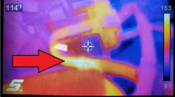
There are multiple ways to check powers and grounds to a module. Some of these techniques, if performed incorrectly, can yield false results and misdiagnosis. Voltmeters and test lights are common tools to perform this task but often result in misdiagnosis if the chosen connections, and subsequent results, are not understood. My preferred method is to load the circuit with a head lamp, which many technicians do, but while performing this test I measure the voltage drop across the headlamp (Figure 1). This provides an additional piece of valuable information. The headlamp I use draws about 4 amps of current which should be enough to make the circuit work without melting a wire. To elaborate, if the headlamp lights we are loading the circuit and know that sufficient current should be able to flow. If we measure the voltage drop across the headlamp and compare it to system voltage, we can calculate the voltage drop in the circuit. In this case, while checking the power to the DDM, the headlamp illuminates brightly and the voltage drop across the bulb is measured to be 12.43 volts. The system voltage on this vehicle is 12.60 volts. Therefore, the voltage drop in the circuit is 0.17 (system voltage – bulb’s voltage drop) which is acceptable. The same procedure was repeated on all the powers and grounds to the DDM with acceptable results.
Next order of business is to check for the ability to communicate. The technique I prefer to use requires at least a two channel scope. One channel is connected to the DLC network pin, in this case pin 2, using a DLC break out box (Figure A). The second channel is connected to the communication wire at the DDM. If the network wiring is intact, both traces on the scope should have an identical appearance (Figure 2). If channel A were to appear as we expect, and the communication signal on channel B looks different, or is missing, then we know that we have a wiring problem. On this vehicle, both traces mirror each other and have the correct network voltages of approximately 0 to 7 volts.


Since we have obtained known good test results during all three of these basic checks we can conclude the driver’s door module has everything it needs to function on the network yet it chooses not to. The DDM was replaced communication is restored with the scan tool. The DDM was then programmed, which is required, to make it work in the vehicle. Power window functionality was restored. The DDM replacement solved all of the issues on the vehicle.
Vehicle No. 2: Erratic instrument cluster operation
Our second vehicle is a 2012 Toyota Corolla. The customer’s complaint is erratic instrument cluster operation. Specifically, warning lamps illuminate for no apparent reason. The gauges also perform erratically, for example: the tachometer bounces around even though the engine is idling smooth. The vehicle does run and drive okay.
Step one is to attempt to communicate with the instrument cluster and see which other modules are communicating on the network. In this case, the Toyota Techstream scan tool is used and it reports that none of the modules on the CAN network are responding. The second step, get the lay of the land, confirms that all of the modules shown in the topology diagram are in fact absent. The next step is to know what good is. In this case, CAN high voltages rest at 2.5 volts and pull high to 3.5 volts while communicating. In addition, CAN low rests at 2.5 volts and pulls low to 1.5 volts while communicating. CAN high and CAN low should mirror each other.
Time to pick our path. Since the entire network seems to have an issue, CAN high and CAN low will be scoped at the DLC using a DLC break out box. Can high and CAN low can be found on pins 6 and 14 respectively. The scope pattern (Figure 3) was obtained and it is safe to say that communication voltages are definitely not what we expected to see.

If we use the data that we have already gathered we can apply the process of elimination to cross a few faults off of our suspect list. Given the scope capture, we can conclude that neither of the CAN communication wires are shorted to ground. If they were, one (or both) of the traces would be very close to zero volts. The same can be said about a short to power, one (or both) of the communication wires would be resting near system voltage. In addition, an open communication wire would disrupt communication with some, or all, of the modules depending on where the open is. However, an open wire would not corrupt the communication signals in the manner we are seeing. If the network wires were to short together the two traces would be incorrect, but they would mirror each other. I think it is safe to cross shorted wires off our list as well.
Time to choose our path. Given the observations outlined in the last paragraph, we can eliminate almost everything other than a single module that is failing and corrupting the communication on the entire network. There are multiple ways to isolate individual modules on vehicles. One method would be finding a splice pack, or common connection, where the network can be broken into individual pieces. In some vehicles, such as many GM products, a splice pack may be easily accessible. Some Chrysler products have a DJP, or diagnostic junction port, that allows us to isolate individual modules. In the case of our Corolla, there appears to be a central junction point on the wiring diagram but it is buried in the dashboard and access will be time consuming. Our option in this case will be to disconnect one module at a time while watching our scope, or scan tool, to determine when communication returns.
For the sake of diagnostic time, the location of all of the questionable modules is identified using service information. The list of modules is then prioritized based on ease of access. For the Corolla, we can put the modules in the following order: A/C Amplifier assembly, Center Air Bag Sensor, ABS module, ECM, Combination Meter Assembly, Power Steering ECU, Steering Sensor, Yaw Rate Sensor and Main Body ECU. Of course, this order could be different based on the technician’s preference.
The A/C Amplifier Assembly was chosen first due to the fact that its connector is visible under the dashboard just ahead of the center console and no disassembly is required to perform the disconnection. Everyone gets lucky sometimes. The scope capture (Figure 4) returned to normal once the amplifier was disconnected. In addition, all of the other modules came back on line and the instrument cluster operation returned to normal.


If the A/C Amplifier disconnection did not solve the problem we would have continued down the list of modules until the desired result was achieved. In this case, replacing the A/C Amplifier Assembly resolved all of the vehicle’s issues.
In conclusion, following the four step plan outlined here will direct a technician through an efficient and effective diagnostic process. In both case studies presented here, a single module caused both faults even though the presentation of these faults was very different. The same process was used to gather data and guide us to successful diagnoses.
To summarize, following the previously outlined four step process often solves network issues. If not, the process can provide usable diagnostic direction while tackling the odd ball issues that don’t fit the norm.