While reading an article in the August 2015 issue of Motor Age, “Breathing free,” I noticed it was penned by a friend of mine — David DeCourcey. I also noticed his article contained a wealth of information regarding potential engine breathing problems. He pointed out that restricted exhaust systems, incorrect camshaft timing and other issues could effect engine breathing. His article got me thinking about the process involved in diagnosing low power, engine breathing or any other drivability issues for that matter. So this month, please allow me to expand on Dave’s article.
As a mobile diagnostic technician, I need to be quick and efficient with my diagnostics so I can move on to the next vehicle. This is no different than a technician working in a shop. One of the keys to efficient diagnosis, mobile or not, is a logical process that is repeatable on any vehicle. The goal of this article is to provide a technique that will accomplish this diagnostic task.
The “repeatable” technique that will be covered here applies to engine breathing issues, but also can be used for a variety of other complaints — low power, lean codes and transmission shifting, to name a few. If we were to test drive a vehicle with our foot to the floor, a technique required to allow the engine to breathe, what would the data on our scan tools display? The data that can be gathered during this type of test drive can be valuable. Let us explore the possibilities.
There are six main PIDs that we need to record while performing this test drive. This wide-open throttle run should include: engine RPM, MAF sensor, engine load, oxygen sensors, MAP sensor (if equipped) and fuel trim numbers. All of these PIDs will be valuable when we step back and look at the big picture. To perform this technique accurately and safely, set up the scan tool to record all PIDs and do a short drive — hammer down! No need to speed of course, the goal is to get air flowing. Once we have gathered the data and returned to the shop, the information can be analyzed.
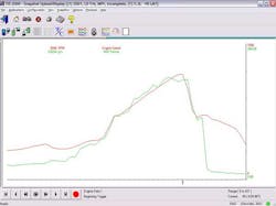
The first step in analyzing data is knowing what good is. For a known good vehicle, the load PID should be in the 80 percent to 100 percent range. However, the load PID can be calculated differently by manufacturer, or even by model or production year. Because of this variable, volumetric efficiency is a viable option. Therefore, the first pair of PIDs we need are RPM and airflow measured by the MAF sensor. Incorporating engine displacement, engine RPM and airflow into a calculation, actual engine airflow can be compared to the theoretical maximum the engine should be flowing. This calculation yields a percentage of how well an engine can breathe compared to its physical limitations. This volumetric efficiency, or VE, calculation can be performed by hand, by calculators that can be found online, built into scan tools or available for purchase though companies such as AESWave.com. Our first scan tool image is from a known good 5.3 liter General Motors pickup truck (Fig. 1). It shows a wide-open throttle test drive and the PIDs displayed are engine RPM and Mass Air Flow.
The red trace is engine RPM and is used as a reference for our test drive. The green trace is mass air flow in grams per second. These PIDs, along with engine size, are input into a VE calculator. The next image shows these numbers input into a VE calculator, DECS, and the VE result is displayed on the right (Fig. 2). The result is 77 percent, which is acceptable for this V8 overhead valve engine.
Known good volumetric efficiency numbers vary depending on engine design. Because of this design aspect, there are no known good specifications for any particular vehicle, nor are there any specifications published by the manufacturers. I find that usually a naturally aspirated engine varies between 75 percent and 95 percent volumetric efficiency. Forced induction engines, with turbo or superchargers, will be higher.
If we were to repeat this test on a forced induction engine, such as a 2.0 liter turbocharged Volkswagen Beetle, we would see different results. The VE calculation is higher because during a wide-open throttle test drive the engine has boost, or positive pressure inside the intake manifold, as opposed to the usual barometric pressure of a naturally aspirated engine. The percentage varies by application and can range from approximately 110 percent to numbers in excess of 150 percent. The particular engine used in this example was breathing at 124 percent of what its naturally aspirated brother would be.
In order to bring those numbers down to a number we can better identify with, we can do some math. If the vehicle is equipped with a MAP sensor, the pressure in the intake manifold can be observed during our test drive. If not, a vacuum/pressure gauge can be connected for the test drive. As an example, we will use a 2015 Nissan Juke with a 1.6-liter 4-cylinder turbocharged gasoline direct injected engine. In this case, boost in the intake manifold was measured to be 13.5 pounds per square inch using the MAP sensor PID. If we know the barometric pressure for the altitude the vehicle is being driven at, and know that one psi is equal to two inches of mercury, then we can do some calculations.
The barometric pressure, at the altitude the test drive was performed, was 29 inches of mercury. If we take 13.5 psi and multiply by 2, we get 27 inHg. Next, we add the 27 inHg to the barometric pressure of 29 inHg to get a total of 56 inHg. Now 56 inHg can be entered into the VE calculator (if your calculator supports this input) as the new barometric pressure. Now the calculation will yield a number that should be near 100 percent. In this case, the engine is breathing at 96 percent of its efficiency with the given boost pressure. For the sake of comparison, the scan tool reported a calculated load PID of 97 percent compared to our figure of 96 percent. The scan tool also reported an Absolute Load PID of 166 percent compared to our calculation of 179 percent. In this case, our load PIDs generally mirror our calculations. In some cases they will not. A major point of using a VE calculator is to gain an understanding of engine breathing and where the load PIDs are derived from.
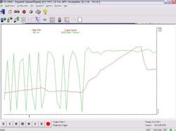
For our second set of PIDs, the oxygen sensors, an assumption of known good would be full rich during wide-open throttle. This can be seen in the next scan tool capture (Fig. 3). The red trace shows engine RPM as a reference and the green trace is the upstream oxygen sensor.
In most cases, the previous statement and image hold true. The PCM is ignoring the oxygen sensors during wide-open throttle because PCM is most likely operating in open loop and subsequently adding fuel to achieve the power desired. However, there are vehicles that stay in closed loop during wide open throttle. Full rich is the most common way to describe a known good oxygen sensor response during a wide-open throttle run, but a better description that applies to most modern vehicles is that the oxygen sensor does NOT go lean. A particular vehicle may have upstream air fuel ratio sensors that do not behave in the same manner as traditional oxygen sensors. On these applications, the downstream oxygen sensors can be used for the same purpose.
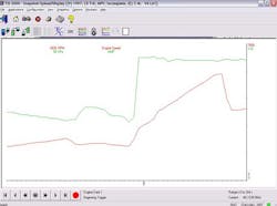
The third PID in question would be the MAP sensor, if the vehicle is equipped with one. During wide-open throttle, barometric pressure is allowed to rush into the intake manifold. As long as we are at wide-open throttle, the MAP sensor should read barometric pressure. The next image, using RPM in red as a reference again, shows the MAP sensor in green (Fig. 4). It reaches and maintains approximately 99 kilopascals, which is appropriate for my altitude.
The last PIDs to concern ourselves with are the fuel trims. These are the only PIDs that we care about when we are NOT at wide-open throttle. That being said, our test drive recording should include some normal driving, as well as the wide-open throttle portion. Plus or minus five percent fuel trim totals can be considered ideal and plus or minus 10 percent could be considered acceptable. There may be some dispute about these specifications in some industry circles, but they can be viewed as a generally acceptable range.
Given the known good data just covered, a scan tool capture of a test drive for a known good vehicle would be as follows: good engine breathing (VE), rich oxygen sensors, an MAP sensor near BARO and normal fuel trim numbers during closed loop.
Next we will look at some broken vehicles. The first vehicle in question has a failing fuel pump. Fuel volume is low, and the vehicle exhibits low power. During our VE test drive, we calculate a VE of 85 percent. Fuel delivery issues should not effect engine breathing because the amount of fuel being introduced has no effect on what the engine inhales or exhales, so this number is acceptable. The next scan tool capture (Fig. 5) shows the oxygen sensor (green) and the MAP sensor (blue) during our wide-open throttle run. The oxygen sensor is observed at a very low voltage, indicating the engine is running lean. The MAP sensor is also observed and it maintains a near barometric pressure reading during the entire wide-open throttle portion of the test drive.
The last PIDs observed are the fuel trim numbers, and they are noted to be higher than normal (positive) under all conditions but worse at higher RPMs. The summary of a fuel delivery issue would be good engine breathing, lean oxygen sensors, an MAP sensor near BARO and positive fuel trim numbers that worsen as fuel demand increases.
The second broken vehicle in question has a bad MAF sensor. The same test drive yields a poor VE number because the airflow we are entering into the calculator is incorrect. Also, the oxygen sensors read lean because the engine is not being fueled adequately. An incorrect air measurement would obviously cause an incorrect amount of injection, open or closed loop. The MAP sensor confirms barometric pressure is inside the intake manifold. Fuel trims during closed loop are positive. In this case we have an air metering problem. This vehicle’s scan data capture would be very similar to the previous vehicle with a fuel delivery problem other than the fact that the VE calculation would be poor.
The third vehicle with an issue has a restricted exhaust. A restricted exhaust can be one of the hardest issues to pick out on a scan tool, especially if the restriction is minimal. A restricted exhaust usually yields a low VE number because the engine cannot exhale. However, air entering the engine is measured correctly and fuel delivery usually appears normal. This normal fuel delivery can be observed in the fuel trim numbers during the closed-loop portion of the test drive recording. Oxygen sensors will also perform close to normal given the amount of fuel being injected into the engine. While observing this data, a restricted exhaust can easily be confused with a restricted intake. However, when presented with the possibility of a restricted exhaust or a restricted intake, which would you check first?
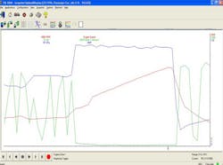
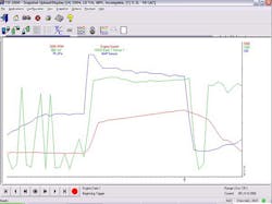
The final problem vehicle has a restricted intake. Airflow is again reduced because the engine cannot inhale, so our VE calculation is low. Airflow through the engine, although reduced, is being measured correctly so the engine is being fueled correctly. Therefore, the oxygen sensors respond appropriately. The difference here is the MAP sensor. A restricted intake acts just like a throttle blade — it restricts airflow and forces manifold vacuum to occur. The next scan tool capture (Fig. 6) illustrates the MAP sensor — the blue trace — moving away from barometric pressure as manifold vacuum builds. The engine RPM in red can still be used as a reference. The third trace, in green, is the oxygen sensor. In this case, the most valuable PID is the MAP sensor in blue.
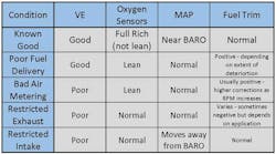
In order to make sense of all of these numbers, I have included a chart (Fig. 7) that illustrates these issues as they relate to each other. The left column of the chart indicates the vehicle condition and the subsequent columns describe each of the PID’s expected behavior.
Each one of these conditions has traits that are not shared with the others. A relatively simple test drive and accompanied scan tool recording can quickly be analyzed and compared to the chart in order to narrow down the number of diagnostic tests needed to isolate the cause of the low power or drivability complaint.
There are however, other issues that can cause low power complaints that do not show up on the chart. Transmission issues, ignition timing problems, torque converter malfunctions or dragging brakes could be examples of these issues. In all of these cases, the test drive results would match the “known good” vehicle.
Valve timing issues will also show up as breathing issues while using this test. It is important to note how the engine is configured on the particular application being worked on. For example, a “V”-type engine with overhead camshafts could have one camshaft that is out of time. Performing this test drive on a vehicle with this type of problem would result in a poor VE number, but there will be some differences in the data. Usually, the oxygen sensor and fuel trim PIDs will move in the opposite direction of one another. For example, bank 1 oxygen sensor might go rich during wide open throttle, while bank 2 oxygen sensor displays lean. The fuel trim numbers during closed loop operation would also reflect a bank-to-bank skew. When this skew, be it oxygen sensor or fuel trim, is noted during the test drive, our diagnostic direction should shift towards an issue that affects half of the engine as opposed to the whole. This observation is also useful in adding the diagnosis of camshaft phaser problems on “V”-type engines with variable valve timing. Of course we need to be aware of special situations, such as vehicles with two ETC throttle bodies and two MAF sensors, but that is a topic for another day.
In summary, a good understanding of engine breathing, how to measure it, how the PCM measures it and how the PCM responds to various conditions is invaluable when it comes down to diagnosis. I am sorry to say that there is no magic solution to solve these issues. It is up to us to be the doctors who properly diagnose and repair breathing issues without the use of snake oil.
