Content brought to you by Motor Age. To subscribe, click here.
What You WIll Learn:
• Get comfortable with the physics involved with ignition system functionality. It can't be changed, and it applied to everything.
• Magnetism and electricity are very closely related
• Mutual induction allows an ignition coil to turn 12V into upwards of 80,000V
I’m frequently asked to analyze many ignition waveform captures from technicians around the globe. This is a skill set that has been hammered into my head since I was a young up-and-coming diagnostician. Why? Because this waveform analysis is the same, regardless of which spark ignition internal combustion engine the waveform was derived from.

Faraday’s law
I will be the first to tell you that I’m not one to suggest memorizing these laws of physics. I do, however, recommend becoming familiar with what it is that they are defining. Faraday’s law addresses what is known as electromagnetic induction. This is the electrical current that is generated in a conductor (or wire) when a nearby/adjacent magnetic field changes in strength (or intensity). Said another way, we can create electricity in a wire simply by moving/changing a magnetic field near that wire.

I told you that to tell you this…This is exactly how ignition coils function on all spark ignition internal combustion engines regardless of year, make, or model. That’s right, at a basic level, an ignition coil operates the same in a 1929 Marmon as it does in a 2022 Bugatti Chiron (Figures 1 and 2). It’s plain to see why this was pounded into my mind so many years ago.
During the 19th century, a physicist named Michael Faraday discovered a relationship between a changing magnetic field strength (magnetic flux) and the electromotive force (voltage) that is induced within a wire as a result. This is what became known as Faraday’s law.
In a recent article of mine, I discussed another law of physics known as Lenz’s law. While Lenz’s law relates to the rate of current flow change in an inductor as it saturates (ignition coil primary windings), Faraday’s law relates to the resulting inductive kick that occurs when that current flow ceases and that ignition coil discharges. And this is the basis for our topic of discussion today (Figures 3 and 4).

Seen here is an experiment to help describe what is to be expected as a magnet is passed through a hollow cardboard tube. Around this tube is an inductor (multiple coils of a conductor or wire). Connected on either end of the inductor are the leads of this Fluke 88 DVOM, set to detect voltage indifference (difference in voltage between the red and black test leads) (Figure 5).
As the magnet (along with its magnetic lines of flux) is passed through the hollow tube, the flux lines cross the inductor coils and induce a voltage indifference, as seen on the DVOM display. In fact, these same principles allow variable-reluctance crankshaft/camshaft position sensors to operate with the signal characteristics they exhibit (Figure 6).

Step-up transformer construction
So, how does this at all relate to the ignition coil, and what is its significance? The ignition coil is a device known as a step-up transformer. It earned that name because an ignition coil operating with only 12-14V can step up that voltage to amplitudes nearing 80,000V on some systems. This is all possible due to the operation of the ignition coil which functions as it does due to Faraday’s law.
I’ll begin by describing an ignition coil as having two distinctive sets of coil windings (inductors). One is known as the primary winding, and the other, the secondary winding. These two sets of windings affect one another through a process called mutual induction (Figure 7).

Mutual induction is described as a voltage being induced in one set of windings because of a change in current (magnetism) in the other set of windings. In other words, a steady current in the primary windings does nothing except establish a magnetic field. The collapsing of that magnetic field (when the current flow ceases) creates the induced voltage in the secondary set of windings.
Primary windings- Regarding the configuration of the coil, the primary set of windings is the set that is being controlled or in which the current is being manipulated. For that reason, this set of windings is larger in diameter (relative to the diameter of the secondary windings) to allow for higher current flow values. It’s common to see primary coil windings carrying 10A or more. However, the length of the primary winding is relatively short (compared to the secondary windings). This allows for only several hundred turns of the inductor.
Secondary windings- The secondary set of windings is much thinner in diameter (relative to the primary windings). The secondary windings do not carry much current or for very long (typically less than 2ms). However, the secondary windings are significantly longer (relative to the primary windings) to allow for at least 100 times more turns of the inductor. For every one turn of primary windings, there are typically 100 turns of secondary winding, and that fact holds some significance. This will be discussed shortly.

Coil functionality
It’s typical to see the primary set of windings supplied with a source of voltage from a fused source and/or a relay (Figure 8). The control of current flow is then carried out by a switching device on the ground side. These switching devices replaced the points/condenser in older distributor systems when the systems were eventually engineered with electronic control, and they have various names (dependent upon the vehicle manufacturer). Some you may recognize from this list below:
- PCM
- ECM
- Ignition control module (ICM) I
- Ignition control unit (ICU)
- Igniter
- Power stage
- Coil control module

Although the names vary greatly, rest assured they all serve the same purpose, to allow electrical current to flow and then to prevent current from flowing.
When the switching device allows for current to flow through the primary windings, this is known as a dwell period. At that time, the primary coil windings begin to take on energy as they saturate. This energy or current flowing through the looping inductor creates a magnetic field around that inductor.
At the time the PCM/ECM decides it’s appropriate to induce a spark (at the spark plug gap for a specific cylinder), the PCM/ECM will end the dwell period by opening the circuit via the switching device. The current that was flowing through the windings no longer flows. As a result, the magnetic field (that built up over the dwell period) collapses.
Electricity and magnetism are very closely related. So, when the magnetic field collapses, that potential energy must dissipate somehow. It does so by transforming from magnetism to electricity within the primary windings.
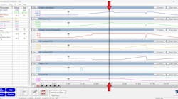
Keep in mind the several hundred turns of primary windings mentioned earlier. Because each turn of the primary windings multiplies the induced voltage, the 12-14V that was used to energize the primary windings is now several hundred volts as the magnetic field collapses, as displayed on the Snap-on M.O.D.I.S. capture in figure 8.
Because the secondary windings are within close proximity to the primary windings, the several hundred volts we just discussed are mutually induced in the secondary windings. What’s more, is the secondary windings have at least 100 times the turns of the primary windings. So, how do you think that affects the induced voltage?
You guessed it; the voltage is multiplied! This now means that the several hundred volts induced in the primary windings becomes tens of thousands of volts induced in the secondary windings. It’s this tremendous amount of energy that is required to create and maintain the spark at the plug electrodes in the cylinder under a tremendous amount of heat and pressure. This occurs as much as a billion times over the life of the vehicle.
.")
Applicable to most
So why make such a big deal about Faraday’s law? The fact remains that even though technology has advanced (and continues to advance) significantly over the years, it’s a common misconception that ignition event acquisition and waveform analysis are dead. I will say it’s a dying art, but it is only because techs think the ability went away with the ignition distributor.
It’s true that acquisition was much easier with the distributor because it offered a very simple and easily accessible test point (at the coil output) to acquire the secondary waveform. With today’s coil-over-plug/coil-on-plug (COP) systems, the secondary waveform is accessible through the implementation of a capacitive pickup, but the COPs are typically heavily shielded to prevent radio frequency interference (RFI). This makes acquisition extremely muted or at times impossible.
However, the primary and secondary waveforms closely mimic each other, meaning the same data can be extracted from either one. An option would be to instead connect to the primary side of the coil. However, unless you are faced with a 2-wire COP, you will have no access to capture the primary voltage waveforms, either. The 2-wire COP is controlled the same as a coil found in a distributor system. The switching device is in one of the controllers in the list mentioned earlier. These systems offer direct access to the primary circuit. Simply connect to the control circuit between the coil and the switching device (Figure 9).
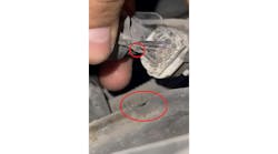
But if you are dealing with a 3- or 4-wire COP, the switching device is internal to the coil, leaving the primary circuit inaccessible. However, there is a solution. Simply pull the COP from the cylinder head and connect a high-tension extension lead between the coil and the plug. This will offer the same secondary waveform acquisition opportunity as did an old distributor system (Figure 10).

Viewing combustion through the eyes of the ignition scope
What technicians frequently fail to realize is that the ignition waveform offers a tremendous amount of information, not just info. pertaining to the health of the ignition components. In fact, here is a list of some of what can be derived from ignition waveforms of today’s newest vehicles (in combination with other tests and under a variety of different engine operating conditions):
- Low cylinder compression
- Lean air/fuel ratios
- Rich air/fuel ratios
- EGR dilution
- Cylinder sealing issues
- Weak ignition coils
- Loosely fitted spark plug wires or poorly installed COPs
- Poor injector spray patterns
- Carbon-contaminated GDI platforms
- Shorted spark plugs
- Excessive spark plug gaps
- Carbon tracking
- Ignition timing issues
- Primary-circuit voltage-drops
- Poorly functioning switching devices/Condenser failure

With the ability to detect such potential faults with one simple connection to the vehicle, I have grown to love ignition waveform acquisition and analysis and implement it frequently. I must tell you that it certainly is not the first test I choose to perform.
In fact, as some of you regular readers recall, I always recommend reaching for the “low-hanging fruit.” The easiest information to grab that offers the most insight is always my goal (which typically begins with scan tool data). But ignition waveforms can provide another “arrow in the quiver,” so to speak. Anytime I can back up my theories about a potential fault with the results from not one but multiple tests, the likelihood of my being accurate in my analysis (or where/what I may choose to test next) is significantly higher.
Take the time to do your diligence. Acquire the tools to perform the analyses on known-good vehicles, and practice often, creating your own faults deliberately and capturing the waveforms for analysis. It’s like my mentor (Jim Morton) always says: “If you become comfortable with what ‘GOOD’ looks like, ‘BAD’ sticks out like a sore thumb!”
Although these acquisition and analytical skillsets are not a necessity, they certainly will be another tool in your belt for driveability concerns. Having the test results to lean on and analyze can be the difference between being confident in your diagnosis and simply hoping for the best outcome with your fingers crossed.
Keep your eyes open for my upcoming ignition class that is currently under development. It should be available sometime in late 2023-2024 and will cover everything you need to know about the physics involved, ignition theory and operation, the correct tools to have, and how to use them. The class will even teach you how to experiment safely so you can grow your knowledge and expand your horizons as an industry-leading diagnostician.