Content brought to you by Motor Age. To subscribe, click here.
Welcome back to another edition of “The data doesn’t lie,” a regular feature in which I pose a puzzling case study, followed by the answers to the previous issue’s puzzle.
What You Will Learn:
• Understand a test's limitation is the key to successful data capture
• Always be conscious of the possibility for multiple faults to exist simultaneously
• With proper training and practice, pressure transducer testing will save you time and increase accuracy
Using specialized tooling to locate engine mechanical faults is tricky at first, but when there is more than one issue, it can seem like an impossible technique to master, especially for a novice.
This case came from great friends of mine at Black Hills Tire in Rapid City, South Dakota. They were faced with a 2014 Ram ProMaster van with a 3.6L V6 engine. The vehicle came to the shop with an overheating concern and a loss of antifreeze from the cooling system, but no visible leaks were present.
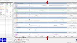
Quick to grab their Pico lab scope, current probe, and delta sensor, they cranked the engine over several times while obtaining starter current (for relative compression), and pressure pulse data from the cooling system reservoir (Figure 1). This data indicates a few important pieces of information pertaining to the health of each of the cylinders, which cylinder is faulted, and most importantly, at what area of the cylinder the fault is occurring.
 indicates a loss of compression for cylinder #2. The cooling system pulse trace (blue) shows pressure change/activity in the cooling system that correlates with the compression loss.")
Previously referencing the firing order in service information and capturing the #1 ignition event (for synchronization of Top-dead-center for cylinder#1) they began their analytic process. It was quite visible to me that there is a disturbance in the coolant reservoir pressure (In blue) that correlated with the #2-cylinder relative compression hump.
Logic would tell you that the #2 cylinder is leaking compression into the cooling system. However, if you look more closely, you can see the blue cooling system pulse trace has been magnified 20x to see this disturbance. Even though there is clear evidence that the cooling system has been compromised and is allowing cylinder #2 to shed its contents into the cooling system, I believed we were dealing with an additional complication. With the amount of loss indicated by the #2 relative compression hump, I would have expected the cooling system trace to indicate a much larger disturbance than what was present (had the head gasket been the only leak point).
 relative compression trace indicates loss of #2 compression, the intake pulse trace (blue) shows no correlating significant change in pressure.")
A second approach
The process was repeated but this time with the delta pulse sensor interfaced with the intake manifold (Figure 2). Like the coolant system pulse trace, this area also delivers a ton of information quite easily. The same #2 cylinder is shown as being compromised (in red). After viewing this data, my question became, “Where is the #2-cylinder compression going?”
Visible in this capture is a lack of significant rise in the blue trace (at the same time that the red trace indicates a leak for cylinder #2). According to the blue trace, what can be determined?
The data doesn’t lie
With all the information in front of us, we were faced with deciding how to proceed. Here are some bullet points of what we knew to be factual, and I will ask all of you, diligent readers, for your input:
- Misfire present; cooling system antifreeze level is low with no visible leaks
- Relative compression trace demonstrates cylinder #2 has a significant loss
- Cooling system pulse trace indicates little rise in pressure when cylinder #2 completes its compression stroke
- The small size of the pulse doesn't seem to correlate with the large relative compression loss
Given this information, what would you recommend doing next?
- Repeat the test and place the pressure pulse sensor in the exhaust system and/or dipstick tube
- Replace head gasket and recondition cylinder head due to intake valve poor seating
- Defer to a different test due to inaccurate results from this test
- Replace head gasket for suspect bank
SOLVED: (April 2023, Motor Age) 2015 Lexus CT200h 1.8L, DTC P261B
What would you recommend doing next, given the data bullet points in last month’s challenge?
- Replace the electric water pump
- Replace the electric water pump relay
- Reprogram PCM to correct for faulty software
- Remove the bumper for further testing, more unanswered questions

For those of you who chose answer #4, congratulations. Even with the already acquired data, we cannot condemn the electric water pump or the relay, nor can we claim that the PCM software is corrupted.
Like any other electrical component, the relay and the water pump must have an adequate voltage and ground supply to function correctly. Referring to the wiring diagram, the water pump and the relay share the same ground.
As the water pump is commanded by the scan tool, the PCM energizes the relay. Current flows through the coil side of the relay (making it a magnet) and draws the switched contacts closed, supplying current through the water pump. With current flow comes heat and voltage drop/resistance.
If the common ground (for the relay and water pump) were in poor condition, resistance at the ground location would create a voltage drop and heat as the pump initially ran. After the pump relay was cycled off/on again, the remaining heat/voltage drop would limit current flow/magnetism through the relay.

The relay switch contact would fail to close at times. But, when it closed, it wouldn’t do so properly. This created an additional voltage drop (across the contacts of the relay) and limited current flow for the water pump to function properly.
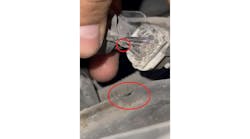
Ground #A3 (beneath the front bumper) was inspected and found to have poor contact due to a recent paint job/body shop repair (Figure 3). The ground location was cleaned/enhanced, and the pump ran as designed (Figure 4).
Be sure to read next month's Motor Age issue for the answer to this month’s challenge and what was discovered!