.")
Content brought to you by Motor Age. To subscribe, click here.
Welcome back to another edition of “The data doesn’t lie,” a regular feature in which I pose a puzzling case study, followed by the answers to the previous issue’s puzzle.
What You Will Learn:
• The variations in system configurations adds complexity, making diagnostics challenging at times
• System description and wiring diagrams can keep your approach logical
• Sometimes investing more time doesn't seem profitable initially, but pays-off in the long-run
Just last month, I found myself neck deep in a 1994 Ford Ranger. For 16 hours of my life, this vehicle left me scratching my head. It presented with one symptom, was repaired, and couldn’t leave because it had a seemingly unrelated new symptom.
The vehicle was towed to a shop as a “crank/no-start” situation. My good friend and knowledgeable tech, Lee, determined the cause was a lack of spark (no coil operation). Lee replaced the crankshaft position sensor (CKP) and ignition control module (ICM) to remedy the situation.
He also got the OK to replace the timing belt because of its age. After he installed the new timing belt, CKP, and ICM, the vehicle was then started without the accessory drive belt installed (Lee simply wanted to verify proper timing belt installation before committing to fully reassembling the engine.) The engine started immediately and idled smoothly. The engine was shut off and reassembly was complete. However, upon restarting the engine, it would barely idle before coming to a stop within a second or two.

Retracing our steps
Aware that the drive belt was not installed during the successful engine start, Lee strategized to remove the belt once again and reattempt an engine start. With the belt removed, the engine started and idled smoothly.
After inspecting the accessory drive pulleys for binding, he found no issue. The drive belt was reinstalled and this time, the alternator was unplugged. A successful engine-start and smooth idle followed. He installed a replacement alternator and battery, yet the same start/stall remained. This is when I was called in for a second opinion.
After hearing the saga, I started and idled the engine successfully with the alternator disabled. Simply remating the alternator’s connector caused an almost immediate stall. I thought it was best to verify there was no charging system issue (such as excessive AC ripple or excessive voltage drop). It seemed logical, as the fault only occurs when the alternator was charging. To my surprise, the alternator was performing properly, and full system voltage was available across the battery posts. I proved this further by once again disabling the alternator and substituting a clean smart-charger power source, only to have the stall occur similarly.

Where do we go from here?
At times we have faced symptoms but no diagnostic direction. These are the times I ask myself about the nature of the symptom. In this case, I'm speaking of the stall. We are all aware that for a stall of this nature to occur, something must be missing from the equation (is it a loss of spark, or a loss of fuel?).
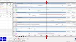
Although I have many different tools in my arsenal, this time I chose to use my lab scope and amp probe from Pico. I chose to monitor the work being performed. More specifically, I was looking for when the work stopped being performed. The engine was either losing spark, losing injector pulse, or a combination of both; the amp probe/scope will tell us that definitively and lead us to the next test.
Although the ignition coil operation always remained (Figure 1), the injector coil current ramps were disappearing (Figure 2). On a separate scope channel, I monitored the control of the injector circuits (measured directly at the PCM connector). This proved the circuits remained intact (no loss of voltage supply to the injectors) but also proved the PCM stopped providing the controlled path to ground for the injectors. On the blue channel, the CKP signal remained intact. This input is used by the PCM to drive the injectors. From this perspective, the PCM should have had what it needed to drive the injectors.
After verifying that the PCM was supplied with adequate battery voltage, ground, and ignition voltage and had a healthy reference voltage output, the PCM was condemned. To my dismay, after two replacement PCMs (one “used” and one “remanufactured”) the fault remained.

Now, it’s ‘personal’
On occasion, I get egg on my face, but the key is, I never walk away with egg on my face. I simply wipe it off. Walking away at this point would yield nothing but sleepless nights. More importantly, if I ever encountered this same issue again, I’d be no better off than I was the first time I had my rear-end handed to me. I was determined to find out the fault.
At this point, I had retraced my steps at least three times, coming up with the same “faulty PCM” diagnosis (which is possible but extremely unlikely). After much research about this vehicle’s strategies and system configuration, I scrutinized a wiring diagram. To avoid any complications, I have access to many different sources of service information. However, this time I chose to use Alldata. For simplification, I redrew the diagram (Figure 3). Although there had not been a loss of spark on this truck, the CKP signal is not sent directly to the PCM. It is first received by the ICM, used to fire the ignition coils, and relayed to the PCM for injector drive/RPM input.
In this configuration, an issue with the ICM could skew the CKP signal to the PCM (“PIP” signal in Figure 3). So, at this point, although I didn’t see an issue with the signal at the PCM, I was still highly suspicious of the ICM being faulty and creating a skewed PIP signal that would allow the PCM to drop the injector control and cause the engine to stall.
The data doesn’t lie
With all the information in front of us, I was faced with deciding on how to proceed and/or how to advise Lee of the proper repair. Here are some bullet points of what we know to be factual, and I will ask all you diligent readers for your input:
- A stall occurs each time the alternator is charging
- The stall is due to loss of injector control (from the PCM)
- CKP signal (“PIP-IN”) appears healthy both before and after alternator charges
- No loss of spark occurs (ICM appears to function normally)
Given this information, what would you recommend doing next?
- Replace PCM
- Overlay new circuitry for fuel injectors
- Replace ICM
- Attempt to locate known-good scope captures in technician forums
SOLVED: (Feb. 2023 Motor Age) 1999 Ford F350 V10 timing fault on one bank
What would you recommend John do next, given the data bullet points in last month's challenge?
- Reassemble the engine and start fresh
- Measure cam lobe peaks with a degree wheel
- Remove the cylinder head for machine work
- Replace PCM due to logic processing error
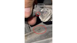
For those of you who chose answer #2, congratulations! After careful inspection and some research, it was learned the camshafts are each two pieces, swaged together with a tight interference fit. Bank #1 camshaft’s front half became disassociated with the back half (Figure 4). After closer inspection, the cam bearing surface showed damage from a lack of lubrication. It’s likely the cam seized, and the timing chain twisted the camshaft apart. This explains why we had a bank #1 fault and why the timing marks were still aligned with no obvious damage to the keyways. Because the cam lobes were out of phase by 180 degrees (360 crankshaft degrees), both banks of the engine were then on the same fire cycle (two cylinders on top-dead-center compression simultaneously).
.")
Answers #1, #3, and #4 are incorrect. There is no reason to reassemble the engine. The data from the relative compression capture proves the engine-mechanical fault. The cylinder head doesn’t require removal because the fault is timing-component related. The PCM doesn’t require replacement because the data collected supports an issue with the engine.
The beauty of a logical diagnostic approach carried out by following the collected data means no guesswork or unnecessarily replaced components. Science drives the analysis, and the data doesn’t lie.
Be sure to read next month's Motor Age issue for the answer to this month’s challenge and what was discovered!