. It was hanging underneath the right headlight and collecting rain water.")
Content brought to you by Motor Age. To subscribe, click here.
What you Will Learn:
• Develop a plan before approaching the vehicle
• Factory service information and OEM information each have their benefits
• Many faults are found because simple, basis steps are skipped
Being a mobile technician means seeing a plan through, and it is very rewarding. I get to see a lot of strange issues and problems that some days make me question my career choice. Luckily, I love what I do and when I finally figure out those tough issues, I get that rush/high that carries me through. That said, I also get called out on many issues that are easily diagnosed with basic testing, research, or understanding of the systems in question.
Now, in my early days (in the bays), I had my share of misdiagnosed vehicles, and I do still make mistakes (just a lot fewer and farther in between). Like some of my current customers, I, too, had a pile of tickets to get through and have made those rash decisions to save time. Many times, it meant I had skipped over the basics and moved further down the diagnostic process than necessary (sometimes influenced by previous problems I had seen or “silver bullets” I had read).
My position now does not allow me the opportunity to make those mistakes because if I misdiagnose now, I am not only putting my reputation on the line, but I am also putting my customer’s reputation on the line. I have learned to develop a solid path with every diagnosis and to never knowingly skip over the basics (even if I have been told they were previously tested and verified).
Unbelievably, I still have customers who have no information systems available in the shop. Furthermore, the extent of their scan tools is a simple code reader. I also deal with body shop techs who are experts in their craft, but when it comes to wiring or communication systems they are about as skilled as I would be in the art of repairing a body panel.
On the path to greatness
Following a consistent path for approaching diagnostics is critical. Regardless of the problem, you start every job by taking the same steps (so you do not miss basic faults or end up taking the wrong turn at the fork in the road). My process may not work for you, but I have found it to work best for me and it maximizes my time. So, take something from it to add to yours, or just find what works for you and go with that.
After I get a description of the problem from the customer, I connect my scan tool and perform a full vehicle scan. I do this even if the problem I am there to fix seems like it would not require a scan (because you may get an open-circuit code or have a new component installed that needs to be set up/configured to work in the vehicle). You may find a code in another module that could influence the problem you are there to look at, or even a completely different issue that the customer is unaware of. Also, never forget the “ever since you” situations. Be wise and save your scans and document your findings. This may be a lifesaver in the future.
While my vehicle scan is running, I perform my visual inspection looking for new components, and recent mechanical/collision repairs (especially those less-than-proper repairs, like an air inlet hose wrapped in duct tape, or vacuum port held on with a glob of epoxy).
I also like to perform a quick battery test. Low battery voltage causes so many communication codes and issues with no-starts because immobilizer systems (and other modules) can lose their configuration during a low-voltage start attempt. Adequate voltage is what allows computers to maintain their memory.
When my scan is done, I review my results and go to service info for circuit description, operation, and diagrams. I pull up code set criteria and TSBs (Technical Service Bulletins) and review some sites for common failures. I have been an independent/aftermarket tech my entire career, so I work on all models. I may think I understand how a system works (because I've dealt with that system so many times on other vehicles) but in different vehicles, that same system may operate differently, which could cause a misdiagnosis.
Having a full understanding of the system/components in question will allow you to develop a targeted approach with “go/no-go” tests to get quick, accurate results. These steps can take anywhere from 10 to 30 minutes, but the time spent doing this could save minutes, hours, or even days (as you will see in the following case studies). These were not difficult issues to diagnose, but they are presented to show how solid processes and understanding save time and prevent misdiagnosis.

Does it need an ECM or not?
We will start with an easy one. This one came from a small local shop that has a very old-school mentality. It has limited scan tool abilities and no information system. It does mostly large mechanical repairs and powertrain replacements.
I was called in to look at a 2013 Hyundai Elantra for a list of codes. This shop owner remembers the early days of computers in vehicles that would set multiple, random codes and would often lead to a diagnosis of a failed module. When I see a list of codes, I think of voltage or ground issues, because a module can only function if it has what it needs to work (including, but not limited to, proper voltage and ground supply).
I started my process and found multiple sensors have already been replaced. I suspect the only reason I was not there to program a “new” module was because of the price of a new Hyundai ECM. The scan showed a list of codes as described. I saw codes for HO2 sensors, the purge solenoid, and the vent solenoid, as well as codes for intake/exhaust valve control solenoids. They were all circuit codes, and a quick review showed they share a common power source (Figure 1).
Testing the fuse revealed it was blown. Installing a new fuse resolved the issue, and I then cleared the codes. Keep in mind that something caused this fuse to blow. Measuring the current in the circuit, I could see no issues. So, I informed the customer to drive the car for a while, but there was a good chance that one of the components already replaced was likely the issue that caused the fuse to blow.
The hesitating Versa
I was initially called upon to program/set up a used transmission on a 2014 Nissan Versa. I arrived to find a dead battery (which is something I see way too often as a mobile tech), so there were no fault codes stored. I proceeded to perform the requested tasks.
Some Nissan CVT transmissions have calibration data for the solenoids stored in the control valve body of the transmission. So, when you replace the unit, the files need to be loaded into the replacement transmission control module to allow proper operation and control of the transmission. Once that is done, it is required/advised (depending on the unit being used or rebuilt, to keep a warranty) to update the software in the TCM to the newest available level. This customer opted for the update as well, even though it was a used unit. After performing the procedures, I took a quick test drive and verified the vehicle was operating properly at that time.
About one month later I was called in to perform the same procedure (but this time on a -remanufactured unit from the dealer). When I asked what happened with the other unit, I was told it was bad from the start. Now in hindsight, I could have asked more questions and pushed a little harder, but here I was a little guilty of being biased because of all the Nissan CVT failures I had seen. I performed the requested tasks and moved along.
The following week I got a call from… (guess who?) … You got it, from the same transmission shop; and guess what? They got a badly remanufactured unit and somehow convinced the dealer to send them another one. I then called “shenanigans.”
When I got to the shop, I told them I was only there to set up the latest unit, but If I had the whole story, I could diagnose the problem with the vehicle. I was told the diagnostic guy was off that day, but I did get all the work orders with the notes. I saw the original complaint of hesitation and check engine light, with a P0705 stored. The notes said they followed the diagnostic flow chart, which led to the transmission needing to be replaced.
At this point, I cleared the old files and loaded the new ones into the TCM and performed the required steps. I then started the diagnostic process. I test-drove the vehicle, and I got the code to set. I scanned for DTCs and found P0705 “transmission range sensor A circuit.” With a quick check of service information, I got the criteria and description of the code. With a quick check for any TSBs or common issues, I located TSB #15-082: 2012-2014 VERSA SEDAN; HESITATION ON ACCELERATION AND/OR DTC P0705 (Figure 2).

This TSB advised looking for indications of moisture in the taillight causing corrosion of the circuit board. The TSB also states that if corrosion is found, replace the tail lamp assembly and not the CVT assembly. One more thing…Before testing, I pulled a wiring diagram for the transmission system. I want to say here that I've been an aftermarket/independent tech my whole life, so the redrawn diagrams are my comfort zone (which can create a problem now and then, so I usually check the OEM (Original Equipment Manufacturer) diagrams as well). The Alldata information system I'm using offers both styles of wiring diagrams.
First, a visual inspection of the taillights indicated a new right-side unit, but the left side was old and showed signs of water intrusion. I removed the back cover to inspect the board and to no surprise, there was corrosion across the circuits. Although I had the exact description of everything in the bulletin, I was not ready to pull the trigger and say, “this is it.” After all, there have been four transmissions in this vehicle up to this point, so I need to verify this truly is the cause.

The transmission circuit diagrams do not show the connection, but if you look at the backup light circuit, it shows that the circuit between the range sensor and the TCM also feeds the backup lights (Figures 3+4).
On this vehicle, battery voltage comes into the transmission range switch. As gear range selection is made, that voltage is sent through the corresponding pin to the TCM to indicate the gear selected. The description of the code says, “two or more range signals say ‘on’ (show voltage) simultaneously.”
If I disconnected the range switch, there should have been no voltage present on the wiring going to the TCM. But, with lights on and the foot on the brake, voltage was present on the reverse wire. If I disconnected the taillight, the voltage would be gone. We now had a confirmed diagnosis, and when I told the service manager, he said, “Huh, that would explain why the parts department asked me if there was water in the taillights when I ordered the second unit. I didn’t look but I just told him, ‘No’.”

The total time for diagnosis (including the research/testing) was between 20-30 minutes. I know some techs are fast, but I am sure that the time I spent researching was a lot faster than swapping the transmission, (even including the time for a third visit to the shop for the same issue).
The flashing Maxima
My last case study was a 2016 Nissan Maxima at a collision shop. The vehicle was previously released to the customer and had returned with a low beam out along with the complaint of the DRLs (daytime running lights) flashing like a strobe when you turn the vehicle off.
The shop determined the aftermarket headlamp was faulty and thought it could also fix the flashing light complaint (well, they were half-right). The low beam worked, but the lights were still flashing. So, they called me in to look. They called me on Friday afternoon, so I did not get there until Monday after the car had sat in a heated shop for the weekend with the battery disconnected.
Once the battery was connected, we saw one flash of the lights, and all was then good. So, now the problem had become an intermittent issue, which is what we all “love” to hear. The shop couldn’t let the customer take the car with the potential of it happening again. Was there a possibility that the battery-disconnection had reset the module, and all is good now? I guess I've seen stranger problems fixed by battery resets, but I'm not OK with taking that chance right now.
So, I began the diagnostic process. The vehicle was already apart, so access to the wiring was a non-issue (Figure 5). I scanned the vehicle, and the only code I retrieved was for a trans shudder (big surprise). I checked TSBs and common faults with no luck. I pulled the wiring diagrams and began my testing.
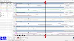
The DRLs are powered through a relay that has voltage supplied via a fuse in the IPDM (intelligent power distribution module). That relay is controlled with a ground that also comes from the IPDM (Figure 6). When the relay is activated, it provides voltage to the lights on both sides.
So, what can cause the lights to come on and flicker? The chance of it being a wire intermittently and repeatedly shorting (while the vehicle is turned off and sitting still) is highly unlikely. At this time, the shop manager stopped over to see what I had found so far. I explained the situation and operation and he concluded that it must be the IPDM (since that sits on the side the deer hit). I advised him that it was a possibility that it was causing the issue, but I was not ready to call anything conclusively until I had evidence.

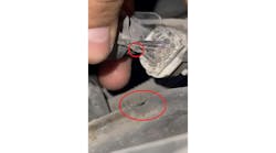
My next step was to locate the relay. The bracket the relay is fastened to had been left unbolted and was hanging upside-down (the light bulb in my head began to flicker). I removed the cover of the relay box, and I removed the relay. I inspected the terminals, and everything looked clean. I removed the case of the relay itself for inspection. Rust and a black, burnt substance on the relay contacts and inside the relay's case were present (Figure 7). The substance was moist to the touch as well.
What I believe happened is the bracket was left unbolted and water had gotten in the relay. Between the water and rusted relay assembly, I believe the voltage was arcing across the contacts and causing the issue. I advised the manager and tech of what I had found and told them to replace the relay and make sure they mounted the bracket properly (so as not to allow water to gather in the relay again).

As you can see in these examples, there is time spent preparing before testing. Understanding how the circuits work (so you can prepare for the proper tests) could prevent wasted time. This might only save you a few minutes in certain circumstances, but it could also be a few hours or even several days in other scenarios, not to mention the amount of money spent on unnecessary parts and the labor to install them. Remember, it’s not only your reputation as a tech that is in question but also the business you represent.