Content brought to you by Motor Age. To subscribe, click here.
What You Will Learn:
• Catalytic converters rarely fail without an underlying cause
• Finding the root cause of the failure is of the utmost importance
• Exhaust leaks, oil/coolant consumption and driveability concerns all contribute to converter failure
I promise, no pets were harmed in the writing of this article.
Wait! What? That car I replaced a catalytic converter in last month… is it back with a P0420 (again)? It must be that inferior quality part you ordered. Oh! Did we get an OEM cat? Umm...
We have all been there. So, let us talk about how to handle it, or better yet, what to do so we do not get there in the first place.
Both P0420 and P0430 are ranked #1 and #2 on the “top-10 most common OBD codes stored” for years. With these statistics, we need to sharpen our skills to get these faults diagnosed fast and accurately.
A quick review of the catalytic converter
Catalytic converters consist of a body/shell typically composed of stainless steel. The inner core is made up of a substrate, a ceramic monolith core with a honeycomb design to maximize the surface area the exhaust gases must pass over (Figure 1).
The substrate is dosed in a wash coat, which consists of numerous chemicals and elements. These initialize the catalytic reactions that chemically alter the harmful exhaust gases to less harmful gases. The precious metals we always hear about in the converters may consist of rhodium, platinum, palladium, cerium, and nickel.
The wash coat may contain all or some of these components and many others. Each one of these components has a specific role in the process. Some are catalyst agents capable of withstanding the extreme temperature in which they work, and others have storage capabilities of components (like oxygen and hydrogen) that are required for the proper operation of the converter.
When the cat stops ‘meowing’ - P0420/P0430
We need to have a proper diagnostic plan to accurately diagnose these codes. I am going to share mine with you:
- I prefer to start with the customer interview to try to get a repair history. I am looking for repairs relating to engine misfires, sensors (inputs), internal coolant leaks, engine oil-burning issues, and such. I also like to ask about smoke or odd burning odors they may have been experiencing.
- I then move on to scanning the vehicle to retrieve DTCs, review the freeze frame, and mode $06 data. The variety of PIDs and info available in the freeze frame has grown significantly to the point where some vehicles have pages available for each code set (Figure 2). I also try to grab PCM software calibration number info while I’m connected with the scan tool, to verify the update level of the software. Sometimes, a change in software corrects a miscalculation of cat efficiency and performance. A road test at this time is also a good idea to determine whether the engine has any other issues pertaining to this repair (low power/runs rough) or not. It is very important to document your findings. Save your freeze frame, save your pre-scan, and make a record of your tests/results.
- This step is essential; consult service information! We need to look at two key items here, the first item being the code-setting criteria and the strategy used to monitor the system. Some manufacturers monitor switch ratios of front and rear air fuel/O2 sensors, and if the rear is switching too often (mirroring the front), then it will set the fault.
- Other strategies monitor the oxygen storage capacity of the converter by running the engine through a set air-fuel ratio cycle. The cycling deliberately depletes the oxygen stored in the converter. The converter is then flooded with oxygen and the fill time is monitored to determine how long it takes to absorb the oxygen to full capacity. This filling is inferred by the activity of the rear O2 sensor. When it signals a rise in O2, it indicates the cat is full and cannot store any more oxygen.
- The second item (this is one I have been bitten by before) is to check to see if there is a TSB that may apply to this code (Figure 3). This is the reason I grab the software/calibration number in the previous step, so I know if the update has already been done. Many vehicles may have a bad converter, but it has been recognized by the manufacturer that a software update, changing the parameters, and operational strategies may extend the life of the converter. Some can be related to a faulty part that is damaging the converter that needs to be replaced, the root cause of a repeat failure of the converter.

What types of failures are there?
The first failure we will talk about is structural. A structural failure consists of a dented shell, damaged threads, flex pipe failures, or cracked/leaky welds. These failures are usually found with a visual or audible inspection. Sometimes the little leaks we cannot see or hear can get tough.
There are a few methods out there we can use to check for these leaks. Some techs suggest using a smoke machine, which I have done, but sometimes this does not work as the converter fights us by absorbing the smoke, or we find a bunch of smaller leaks down the line.
Another method is using a shop vacuum (I have also used a small rechargeable leaf blower) with a rubber tip connecting the hose of the vacuum to the output port and then connecting the other end to the tailpipe (skilled engineering may be required here). Simply fill the exhaust system with pressurized air. I want to point out this works much better on a cold system because if you cannot hear the leak, you spray soapy water and look for the bubbles (hi-tech, right?) If the exhaust is hot, the water will boil off before the leak can be found (Figure 4).

The leaky exhausts can skew a cat’s performance in two ways. First, if there are leaks upstream of the air-fuel ratio sensor, it will alter the ECM’s fuel control strategy (which can lead to damage to the substrate). The second is if a leak exists after the primary air/fuel ratio sensor but before the downstream O2 sensor. This will cause false oxygen to be detected, which again may alter the fuel strategy, but it could also skew an oxygen capacity storage test result and trigger a DTC.
The second failure is not as common but requires the mentioning of thermal shock. The converter’s normal operating temperature is anywhere between 500 to 1,200 degrees Fahrenheit; now drive that through a nice cold puddle, and we get a thermal shock.
Thermal shock is the sudden contraction of the materials that occurs with a sudden drop in temperature. This can cause the substrate to be crushed or damaged and break free to become a rattling converter. Construction design improvements and the use of heat shields have made these faults less common.

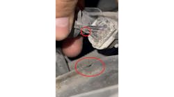
The third failure is poisoning. Poisoning is harder to diagnose without disassembly because the evidence is internally on the substrate internally. This typically comes from antifreeze or oil being consumed during the combustion process and contaminating the substrate (this is why I question the customer about recent repairs).
The system can also be poisoned by fuel or oil additives and the use of improper sealants, especially on the exhaust gaskets (I have seen assorted color rubber sealants holding flange gaskets on). Depending on layout or construction, we may be able to remove a sensor and see the substrate with a borescope. If not, this is one of those situations where you eliminate all the other possibilities and explain the required steps to the customer. I live in the northern half of the country, where road salt is utilized and rust thrives, so it is not likely that we can just unbolt a flange for a quick peak & reassemble.
I saved the best for last, overheating and melting of the substrate. When the exhaust gas levels get too high (whether it be from misfires or incorrect fuel control), the reactions in the converter and the associated temperatures rise above normal operating temperatures. Overheating destroys the active components of the wash coat, making them inert and unable to perform their tasks. Melting is when the temperatures get so hot the substrate melts and starts to restrict the flow of the exhaust gases. This can result in a loss of power because the engine can no longer breathe properly.
If we have followed our diagnostic procedures and eliminated the first three causes, TSBs, and previous repair issues, we now get into the meat of the testing. This is not a problem though because we already understand the criteria for setting the code and the method the ECM uses to determine the fault.
I like to do easy testing methods whenever possible. Don't get me wrong, I love using my oscilloscope when it is required, but this can be handled with most scanners. If the vehicle in question is using switch ratio to determine the fault, we should up our scanner to read the data PID graphs for the upstream and downstream sensors. Essentially, we would be monitoring the same data the ECM does to determine the switch ratio under the same (or as close to the same) conditions as the ECM does. I know what you are thinking… “If it has an air-fuel ratio sensor, we cannot read it.” We can; we just need to read differently.

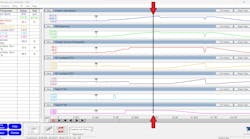
If we look at the current (or amperage, in “uA”), it will be of smaller amplitude, but it will still be a swing. This picture demonstrates the data being monitored while I was testing oxygen storage capacity (Figure 5). You should notice sensor 1/1 signal movement with the lambda value and how it changes with the mixture. Not perfect, but it works. If we see either sensor not behaving as anticipated, we then need to test their functionality to ensure they can perform their job properly. The sensor needs to be able to read rich and lean mixtures and react fast. A biased sensor (one that favors rich or lean readings) can and does cause a lot of converter issues.
The systems that employ oxygen storage capacity test strategies may require a little more effort, but we can alter the mixture with vacuum leaks and alternate fuel sources while watching the reaction time. Or, as I’ve said, I like “easy,” so I get out the scan tool and monitor upstream and downstream (as described above). However, this time, I take the vehicle out on a road test or elevate the RPM in the bay. I then allow the engine to idle normally, give it a wide-open throttle snap, and watch the response time of the downstream sensor before it starts reading oxygen (see Figure 5).
I also use tools that perform the tests for me (Figure 6). This tool guides you through the steps and then calculates the results (this is only one of many useful features for testing fuel control systems). I like this tool for the way it lists its mode $06 data as well. (Figure 7). The actual purpose of our testing is to verify the ECM is getting fed the proper data from the sensors, and then responding properly and as expected.

Valuable information available
The last two resources available are freeze frame data and mode $06. The freeze frame data may be too slow to catch glitches that set DTCs. For P0420/P0430 it puts us in the general range when the fault happens.
We need to review this data to see if any readings were off (not completely out of spec to set a code, but enough to change our air-fuel mixture). The scanners we are using give us an overload of PIDs and I have found myself guilty of passing right by some PIDs that were indicating some issues without me realizing it.
The freeze frame has a smaller list of relevant PIDs and displays those for you to see at the approximate time the fault was detected. Look at the PIDs that can affect the fuel mixtures (like the temperature of the engine and air, MAF or MAP sensors, and the upstream & downstream o2 sensors).
The other source of information we have is mode $06. Although it was not initially intended for us to use as technicians, and some of the descriptions of what is being tested are not perfect, it is a treasure chest of info.
The screenshot I shared is from a good-running vehicle with no faults (see Figure 7). You can see the information provided here and what the computer is using for its parameters to set faults. Why is this valuable to see?
What occurs when parameters are close to failing but just not crossing the threshold yet? Could they be affecting the ECM’s decision for fuel mixtures? You bet! I am from a state where we perform mandated emissions inspections. These consist of reading the OBD2 monitors to see if all or most (depending on the year) have run and passed.
Sometimes monitors will not run, and we will find the culprit in mode $06 data. We could easily see if one of those sensors was close to failing. In other words, we can now see the “gray area” (not just “black and white”). This might be the root cause that prevents a monitor from running.
Some other key data shown is the misfire parameters. Although there may not be any misfire DTCs, there may be misfires occurring (just not enough to cross that threshold of turning the MIL on), but over time can be a culprit to the early demise of our dear old cat.

I’m honest when I say ECMs and scan tools process data faster than I ever could, but despite what every customer thinks about these magic machines, they do not tell us what is wrong with their car. It is still our task to analyze the data and diagnose the faults. We do this by following a process of logical testing which leads not only to the faulty component but beyond that, to what caused that component to fail in the first place.