Content brought to you by Motor Age. To subscribe, click here.
Due to the tremendous feedback received for my Facebook posts over the years of what I refer to as interactive case studies, we are bringing them back! Each month, Motor Age will feature a fresh case study with inquiries of what the next diagnostic step should be. The answer will be revealed in the following issue along with a new case study. How confident are you in your diagnostic approach? I guess you shall see! Best of luck to all of you. — Brandon Steckler, technical editor
What you will learn:
• Use easy-to-perform tests to gain a sense of direction
• Become familiar with tools/test procedures and learn to trust test results
• The data NEVER lies
Like any skillset, mastery takes an investment of freetime. And once you’ve mastered the skillset of data analysis, it tends to look easy from an onlooker’s perspective. However, getting to that point takes practice, patience, and a ton of hard work. The point being, you can lean on the data once you learn to trust it, because the data never lies.
This case begins with a request for a second opinion from my good friend and fellow diagnostician, John Hufnagel (of John’s Mobile Diagnostics). John was faced with a 1999 Ford F350 with a V10 engine. The vehicle initially came to the shop with a timing fault on one bank of the engine (this was previously confirmed with disassembly and with visible inspection). Only the timing components were removed and replaced (by John himself) and the engine was assembled by the book. But after starting the engine, John confirmed that all five cylinders of bank #1 were misfiring and under all operating conditions.
.")
Establishing a baseline
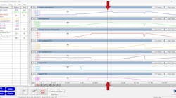
Like any efficient diagnostician, John began with a simple test that would yield him a lot of information about the nature of the full-bank misfire issue without much time invested. He began with a relative compression test (Figure 1).
As can be seen, this is the relative-compression test with ignition events. Two subsequent ignition strikes are those of #1 ignition coil. Together, they represent one complete engine cycle. This V10 engine should produce (you guessed it) ten relative compression peaks. The results of the relative compression test confirmed John’s suspicions of a mechanical engine fault but simultaneously offered some very valuable clues that left him with more questions than answers. John reached out to me with this info, and we both agreed that something was drastically wrong with this V10 powerplant.
To gather more information supporting the strange presentation of the current engine mechanical data, I had suggested John remove a spark plug and obtain a cylinder pressure waveform/ignition strike from either bank of the engine. Bank #2 (without fault) displayed a normal looking pressure waveform with a properly correlating ignition strike (just where we would anticipate occurring, right before peak compression). However, bank #1 (the suspect bank) told a different story (Figure 2).
The pressure waveform looked just fine. However, the spark event was almost exactly 360 crankshaft degrees (180 camshaft degrees) later than expected. This data confirmed our findings and justified the need to invest more time in pursuing an engine mechanical fault.

The path of least resistance
After viewing these captures, I had thoughts on what might be wrong and where to test next, but John is savvy and took the words right out of my mouth. Before I could say anything, he was off to obtain a correlation waveform.
The correlation waveform is just as it sounds. It’s a comparison of the signals from both the crankshaft position sensor and the camshaft position sensor(s). The timing of these signals (compared to one another) can indicate if a camshaft is out of place, if you are familiar with what they should look like.
To save time, I’ve omitted the “known-good” waveform (from a library), but I can assure you, the correlation waveform of our engine was an identical match. So, although the latest data is contradictory to the previous data, we must consider the limitations of the test results we have obtained. Technically speaking, the signals are generated from a tone wheel affixed to the nose of the camshaft. The waveform showed that the tone wheels were in proper alignment. There was a strong possibility that the camshaft was damaged at the location of the tone wheels. No one likes to hear “the engine has to come back apart,” and I’d never recommend doing so unless I was confident. At this point, disassembly was justified.
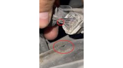
Another afternoon had gone by, and I had received a picture of the timing components from John after disassembling the engine again. The marks compared identically to what was indicated in service information. However, John has not displayed the points where the tone wheels connect to the camshafts. He then removed the tone wheel fasteners at the nose of the camshaft and revealed a lack of damage (and more importantly) that the tone wheels and camshaft were properly indexed to one another (Figure 3).

The data doesn’t lie
With all the conflicting information in front of us, John and I were forced to retrace our steps. I will list some bullet points of what we know to be factual, and I will ask all you diligent readers for your input:
- All of bank #1 cylinders are misfiring under all operating conditions
- The relative compression test shows a mechanical fault with only five (of the 10) compression peaks shown
- Correlation waveform reveals the camshafts’ tone wheels are properly timed
- Visual inspection of the camshafts reveals no damage to the indexing point with the tone wheels (infers the camshafts are in time)
What would you recommend John do next, given the data bullet points above?
- Reassemble the engine and start fresh
- Measure cam lobe peaks with a degree wheel
- Remove cylinder head for machine work
- Replace PCM due to logic processing error
Be sure to read next month's Motor Age issue for the answer and what was discovered!