Content brought to you by Motor Age. To subscribe, click here.
What You Will Learn:
• Understanding Lenz's law will help improve your diagnostics
• The amp probe/scope are a great, visual way to display the work being performed in the circuit
• We can't change physics; that's the best part about implementing the laws in your diagnostic routine

Just as Ohm’s law basically demonstrates how amperage (current flow), voltage (electrical pressure), and resistance (opposition to current flow) all relate to each other, It’s Lenz’s law that allows us to view the functionality of the components in the electrical circuit. Just because a command was given doesn’t mean a function was carried out. If you don’t believe me, simply instruct your child to clean his or her room, and you’ll quickly realize a command doesn’t always produce the intended goal.
Back in the 1800s, a physicist named Emil Lenz discovered that as current flows through a circuit, a magnetic field is created around that circuit. This magnetic field hinders the flow of electrical current. It was this observation that led to what we know as Lenz’s law.
Laws create rules and anticipation
What’s important about laws of physics like Lenz’s law is that it governs how the characteristics of electricity exhibit when a circuit is energized and functioning properly. As mentioned above, as electrical current flows through a circuit, the magnetism created as a result limits the ability of the current to flow.
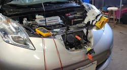
When implementing a digital storage oscilloscope (DSO or lab scope) in combination with a current probe we can see the effects of current flow changing over time. This occurs because the current probe (when encompassing a conductor of an energized circuit) is designed to measure the magnetic field created around the conductor (Figure 1). The key is the magnetic field is proportional to the amount of current flowing (more current = more magnetism).
The current probe will output a small voltage that is proportional to the amount of measured magnetism. The end result: The current probe will output a voltage that correlates with the measured amount of current. Just as an ECU correlates a sensor’s signal voltage input to a physical quantity such as temperature, angle, or pressure.

In use with a scope, this of course offers a visual representation of the circuit’s functionality. We can see not only the command being given but also the response of the circuit activity by way of how the current is flowing through the circuit (or not properly flowing through the circuit).
Why is this important for diagnostic purposes? As diagnosticians, we can “see” the effects of the circuit’s behavior through the eyes of the scope/amp probe. We can do so without disassembly, and equally as fascinating, we can do so remotely. Since the current flow is the same anywhere in a series circuit, we can obtain a current signature from an amp probe anywhere in that series circuit (more on this in a future article). We can capture this information easily and efficiently without disassembly. It’s truly a game-changer in the world of diagnostics, especially considering how challenging it has become to gain access to certain components in today’s tighter vehicle configurations.
Below are examples of common automotive actuators we as technicians encounter on just about every single vehicle we are challenged with. Regardless of what the manufacturers name these devices, it’s the operation of these devices that remains the same in almost all vehicles. We cannot change physics, so why not learn to anticipate the signatures produced by these devices’ circuits when they are in operation?
 but the missing pintle hump means the clutch did not engage. The air gap is too excessive for the magnetic field to overcome it.")
Solenoid current signatures
Call it what you will:
- Solenoid/relay
- Evap purge valve/vent valve
- Fuel injector
- A/C compressor clutch field coil
All these devices are basically the same, and so are their operating characteristics. These are inductive devices, meaning when electrical current is flowing through the conductor magnetism is created. However, this conductor is wound many times over, making it an “inductor.” The significance of the inductor is that each coil winding of the conductor amplifies the magnetic field strength more and more. We capitalize on the strength of magnetism to create physical movement.
We can all relate to this by simply holding two magnets near one another. If the poles of the magnets are opposite, the magnets tend to pull each other together. However, the opposite is true if the poles are alike. They will repel/push away from one another. It’s this physical trait that allows all the above devices to do what they do when an electrical current is flowing through them.
The first characteristic one should notice in the scope current signature is that the current doesn’t shoot straight up but instead appears to ramp in over time. This is Lenz’s law at play (Figure 2). As the circuit is energized and the electrical current begins to flow, the windings of the solenoid’s inductor begin to dwell and take on the electrical energy, which creates magnetism.

Remembering that magnetism hinders current flow, the solenoid’s windings initially take on a lot of energy. As the solenoid windings dwell, the rate of magnetism created begins to dwindle as the solenoid windings become more and more saturated (just as you become less hungry as you continue to eat more of the meal on your plate). It is for this reason the current flow increases over time.
The second significant characteristic is the actual peak current value. This is governed by Ohm’s law (the relationship between voltage, amperage, and resistance). If the total current flow (highest amplitude of the current signature) has reached the amplitude expected, it only makes sense that the available voltage supply and ground supply are not compromised and the resistance value of the solenoid and the rest of the circuit must be proper. Any change in voltage/ground supply or resistance anywhere in that circuit would alter the current being detected by the amp probe and reduce the amplitude of the signature displayed on the scope screen (It wouldn’t have reached the 3.5A displayed).
The third significant characteristic is what we commonly call the “pintle hump.” The current flowing through the inductor and creating the magnetism is what creates the purpose of the device known as the solenoid. The magnetism is strong enough to pull a spring-loaded pintle valve off its seat against spring pressure. This would be the point where a relay clicks and the injector delivers fuel, or an A/C compressor clutch engages (in this example).
Magnetism creates the physical shuttling of the pintle. As the pintle moves, it too creates a disturbance in the current flowing in the circuit. This is described through another law of physics (Faraday’s law), which will be discussed in another article.
As the pintle moves within the magnetic field of the inductor windings, the voltage its movement creates counters the current/magnetism created in those same windings. This counter-voltage opposes current flow.
As a result of the counter-voltage, the momentary reduction in the current flowing creates the pintle hump in the signature on the scope screen. The physical movement of the pintle is being witnessed (confirming the relay clicked, the injector opened, or the compressor clutch engaged). Equally as important is if the anticipated pintle hump is missing, it infers that the device didn’t function as intended, and more time to investigate why is justified (Figure 3).
From this same capture, we can see that the peak current flow is the same as when the device functioned normally in the previous capture. This indicates no electrical fault present (same 3.5A measured) but likely one mechanical in nature, preventing the pintle from shuttling (this A/C clutch had an excessive air gap issue).

Step-up transformer signatures
The job of the step-up transformer is to take an input voltage such as source/battery voltage) and step it up to a higher voltage value. We’ve seen this device for nearly 100 years as the ignition coil. The coil is a necessary device because it can produce enough electrical potential to jump the spark plug’s gap within the pressurized combustion chamber.
Very similar to what was described above for the solenoid current signature, the ignition coil signature also displays as a ramp, and for the same reasons described by Lenz’s law (Figure 4). Magnetism and electricity are very closely related. As the ignition coil takes on energy and the current signature ramps up, the magnetism is generated over time (in this case, several milliseconds). However, when the ignition coil dwell ceases, this is when the coil discharges and a spark is output. The resulting ignition firing event correlates with that point of the coil current ramp.
In this faulted capture, although the peak current value is roughly the same, we can see that the coil ramp is relatively steep when compared to the known-good capture of Figure 4 (Figure 5). As you are aware, the current trace displays current over time. This steep rise indicates an increase in coil current (due to a shorted inductor winding).
It’s logical to question why a misfire may be experienced with a coil shorted in this manner. Let’s think this through:
- A shorted coil causes an increase in current flow (less resistance)
- An increase in the current flow should yield an increase in magnetism. This should yield an increase in coil output, but it does not; why?
When the windings of the inductor are shorted, the path for electrical current bypasses several of the windings. Of course, this reduces resistance and increases current, but there is less magnetism due to fewer energized windings; this results in less coil output. If coil output is reduced to the point that an adequate spark event cannot be sustained, a misfire will occur.

DC motor signatures
Like the other two devices described above, the DC motor is also an inductive device. The same principles apply because it is the magnetism created around the armature of the motor that opposes the magnetism from the permanent magnets surrounding the armature (causing repulsion). We can monitor the operation of a DC motor with a scope and current probe in the same fashion.
As can be seen in the current trace, the initial high-amplitude spike is what is referred to as inrush current (Figure 6). By now, you should be familiar with why this occurs. Upon energizing the DC motor circuit, the current rushes into the windings. As the windings begin to dwell and take on energy, a magnetic field is created, that opposes the permanent magnets and causes the motor to spin.
The rotating armature creates its own counter-voltage (like the moving pintle of a solenoid). As the armature spins faster, more counter voltage opposes the initial current flow and creates the reduction of current flow seen in figure 6. Although there is more diagnostic value in this capture (as it can also be used preliminarily for engine health analysis), this will not be discussed in this article.
Being able to recognize these characteristics and understand the principles of DC motor operation will allow us to recognize when faults are present, preventing operation or allowing intermittent symptoms to surface.
Seen here is another current signature of a starter motor (DC motor). However, this one displays a fault. The symptom exhibited is an intermittent very slow engine cranking condition (Figure 7). The telltale characteristic of the failure exhibits as rapid changes in current flow. This is visible even when the symptom isn’t present.

The significance is in the design of the DC motor. Spring-loaded brushes contact commutator bars that allow current to flow through the rotating armature. As these brushes age and wear, the contact area of the brushes and bars degrade. If poor contact is made, the current flowing through the armature is reduced, and (you guessed it) so too is magnetism. This is what causes the intermittent slow-cranking condition the customer complains about.
The significance is the symptom exhibited mimics that which is created from a dead battery, but it’s the results of the test that tell us what truly is deficient in the circuit. Finding success in implementing such testing techniques takes the appropriate tooling and a lot of practice. However, it would all be a game of memorization without an understanding of the physical laws at play in the captured signatures we rely on for answers.
The voltage in a circuit designed to perform work (actuator circuits) is simply the command to operate. It’s the current that tells the story about the circuit’s functionality. Invest in a scope and current probe and watch your diagnostic success increase many times over.
Being able to see a circuit’s functionality is a game-changer. It takes our diagnostic skillset to the next level. Regardless of how often your diagnoses are correct, without being able to prove component functionality you are indeed guessing.
These tools and testing techniques will take the guesswork out of typical diagnostics and propel your success and confidence in the work bay forward. The best part is all the vehicles we encounter basically function the same. The data doesn’t lie!