This problem vehicle was a 2005 Ford Crown Victoria 4.6L V8 with a complaint of sometimes being hard to start. The retired owner of this Ford does not drive it much. In fact, this vehicle only had 25,000 miles on the clock. The first test that we performed was the standard load test on the battery where we programmed in half of the Cold Cranking Amps (CCA) in to our load tester. If the battery is good, the voltage should not go below 9.6 volts.
Like This Article?
Check out related training at
Diagnosing Body Modules with the Scan Tool
April 25, 2-5:15 p.m.
This battery failed the test big time, with the voltage dropping down to 8.1 volts. Next, we charged the battery up in order to perform a starter and alternator test so we could rule those components out as a cause of the battery’s failure. The testing found that the starter and alternator were good, so it looked like a simple fix requiring only a replacement battery.
A few weeks after we performed the service, we received a call that the Check Engine light was now illuminated on this Crown Vic. As I’m sure you’ve experienced, the owner was thinking that we had something to do with his bright glowing Malfunction Indicator Lamp (MIL). All we did was install a new battery, but as the saying goes, “Once you touch it, you own it!” We had the customer bring the vehicle in so we could check it out and see what caused the MIL to come on.
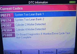
After hooking up our scan tool, we found the PCM had stored the following Diagnostic Trouble Codes (DTCs): P0171, P0174, P0302, P0304 and P1000 (Figure 1). With two DTCs indicating system lean problems (P0171/P0174), the two misfire DTCs (P0301/P0304) could just be a result of the engine’s lean condition. We knew that we had something that was affecting both banks, because both lean DTCs were present. After checking the data stream, we found what we were looking for. Both Short (STFT) and Long Term Fuel Trim (LTFT) values were way out. Because the data stream confirmed the P0171/P0174 DTCs, we knew that we had to concentrate on something that was causing both banks to run lean.
Let’s review what can cause such high LTFT numbers. Now, stop believing everything you read on the Internet and don’t make the awful mistake of thinking that all Fords have problems with their Mass Air Flow (MAF) sensor. While it is a common pattern failure on older Fords, always remember to test and confirm before condemning a part. We know many techs have encountered a bunch of bad Ford MAF sensors, but I’m sorry to say that you would be dead wrong condemning this one.
The MAF checked out OK, so what next? How about a major vacuum leak? Would that affect both banks? Maybe, but once again that was not the cause of this problem. Our next step was to go with something that can also affect both banks — fuel delivery.
A fuel delivery problem can be a result the following:
1. A voltage drop in the fuel pump circuit
2. A clogged fuel filter or other restriction to fuel flow
3. A bad fuel pump
4. A failed pressure regulator allowing fuel to dump back to the tank
Narrowing this fuel trim problem down was not going to be hard. We were going to use a very simple test called current ramping. We perform this test by using an amp clamp and labscope on the fuel pump circuit. Why should we current ramp? There are two simple reasons: (1) it’s the quickest way to see how a fuel pump is running and (2) it’s the easiest
way to see how a fuel pump is running. Quick and easy is good, right? If you are not familiar with fuel pump current ramping or just a bit rusty at using your amp clamp and scope, don’t worry. Whether you are a pro or a novice, we will have you understanding and testing fuel pumps like a pro.
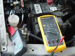
We need to know where to connect the amp clamp. Going to the fuel pump wires would work, but they are usually buried. The best option is to locate the fuel pump relay circuit. If there is something else in the circuit that the relay controls, like ignition or injectors, then go directly to the power or ground wire for the fuel pump and clamp at that point. In most cases, you can use a suitable fused jumper wire and connect it to pin 30 and pin 87 (in the fuse box) or to the fuel pump fuse (Figure 2). Just make sure that there is nothing else powered on this circuit except the fuel pump.
Now that you have located the correct source to the fuel pump, you should set up your equipment properly to get the best possible waveform. First let’s take a look at how to set up the most common amp clamps.
1. Make sure the 9 volt battery in the amp clamp is good.
2. Select 100 mV/A. This is the best setting to use for the finest resolution on your labscope.
3. Connect your amp clamp to your scope and zero it.
4. Select 100 mV per division or 1 V per screen on your labscope.
How to tell if the waveform is good or bad is not that hard, especially if you can compare the signal to a known good. It’s a great idea to save waveforms on good running vehicles for comparison in the future. If the amperage was below normal, it could indicate that we have a voltage drop in the circuit or a bad pump; if the circuit has normal or above amperage, that would rule out a voltage drop problem.
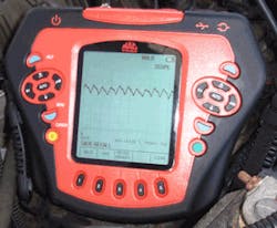
Take a look at this OTC/MAC Tools labscope (Figure 3) and count up the vertical lines. Note that the labscope is set to 0.1V (100 mV) and starts its counting amperage up at the A (look at the lower left corner above the SAVE RECALL). The A is where zero amps starts and each vertical line above it equals (1) one amp. Make sure to go to the top peaks of the waveform in order to come up with the correct amperage reading. See, who said it’s hard to current ramp and come up with an accurate amperage reading?
The labscope is displaying 7 amps on this vehicle’s fuel pump, which is higher than what the reading should be. The reading could indicate a bad fuel pump due to the armature binding or a restriction in the fuel system. I always like checking the easiest and cheapest component first and in this case that’s the fuel filter. We replaced the fuel filter and rechecked our current reading. The amperage of the fuel pump was now down to 5.5 amps, a more normal range for this car. Afterward, we cleared the DTCs and reset the Keep Alive Memory (KAM), performed a test drive and took another look at the STFT and LTFT data PIDs. With the restriction removed, and fuel volume restored, the system lean and misfire issues disappeared. On to the next car!


