Being neighboring countries, Korea and Japan have managed to enjoy a close relationship from ancient history to present day. As a result, similarities can be observed in both their development and economic growth. This little piece of history becomes interesting when we consider the similarities seen with transmissions being used in Mitsubishi, Hyundai and Kia vehicles. Perhaps I should re-phrase this to say, it is interesting to know the similarities, but very essential to know the differences.
Let’s consider the front wheel drive five speed transmission. With this transmission being in three different car manufacturers, more than several different names have been designated to identify this transmission. You will see names like the F5A5A, the F5A51, A5HF1 or the A5GF1 for this unit. These transmissions can be found here in North America in the Mitsubishi Eclipse and Galant, Hyundai XG300/350, Sonata, Santa Fe, Azera and Entourage as well as Kia Amanti, Sedona and Sorento.
To break this down a bit more, this five speed transmission can have six or seven solenoids on the valve body. All Mitsubishi applications using this transmission will have six solenoids. Only Hyundai and Kia can this transmission have six or seven solenoids (If you see a unit with only five solenoids, this is the previous 4 speed version called the F4A40/50 series transmission).
There are a couple of ways to know if the Korean applications are fitted with six or seven solenoids. One way is to look at the solenoid case connector. If there are 10 terminals it is a six-solenoid arrangement. If there are 12 terminals, it is a seven-solenoid arrangement.
Another method is to look at the identification number etched into the case. If the first digit is the letter Q, it is a six-solenoid arrangement. If it is a U or a V, it is a seven-solenoid arrangement. The U typically is a 3.333 overall gear ratio transmission (third digit: K) while the V is typically a 3.311 (third digit: J). The first digit letter also identifies the name of the transmission. The Q means it is the F5A51 transmission. The U is the A5HF1 and the V is the A5GF1. The second digit in the identification number indicates the year. The example shown in Figure 5 is a 2006 A5HF1 3.333 ratio transmission.
Now knowing that Hyundai and Kia could have six or seven solenoids, why the extra solenoid and what effect does this difference make with the operation of this transmission? This is a good question to ask and is essential to know the answer if you would like to diagnose this transmission correctly.
To begin to answer this question, let’s first identify the six solenoids used in both configurations. Looking at Figure 6, beginning on the top left side of the valve body is the Overdrive Solenoid (OD). Next down is the Low/Reverse (LR), and below that the Reduction Brake (RB) solenoid. Top right is the Underdrive (UD), then the 2nd Brake (2B), and below that the Torque Converter Clutch or Damper Clutch Control (TCC/DCC) solenoid. These six solenoids are responsible for both shift sequencing and shift feel.
The seventh solenoid that was added, which is located at the bottom left side of the valve body, is called the Variable Force Solenoid (VFS). This solenoid is used for finer line pressure control as well as allowing for lower line pressure to occur during idle. With six solenoid valve bodies, approximately 130 psi is seen in gear at an idle, while approximately 60 psi is seen with units using the added VF solenoid. This added strategy offers improved fuel economy, as there is less effort for the engine to turn a pump with 60 psi as opposed to 130.
The addition of this VFS for the purpose of fuel economy was not the only change that took place. The components used to make the 3-4 and 4-5 shift also have changed. The clutch application chart is for the six-solenoid valve body configuration. There are three components to observe in this chart: the 2nd Clutch, the Direct Clutch and the Reduction Band.
The 2nd Clutch is applied for 2nd and 5th; the Direct Clutch is applied for 4th and 5th while the Reduction Band is on for every gear except 4th and 5th. Compare this to the application chart for the seven-solenoid configuration. Notice that the 2nd Clutch is used for 2nd, 4th and 5th. They added the responsibility of 4th gear to this clutch. Meanwhile, the Direct Clutch is applied for 5th gear only now, while the Reduction Band is on for every gear except 5th.
These are notable differences to take into consideration when diagnosing any shift concerns from 3rd to 4th and 4th to 5th. The Reduction Band and Direct Clutch would be areas of concern for a flare 3-4 shift with a six-solenoid set up. These same components (should they malfunction) will cause a 4 to 5 flare on the shift with seven-solenoid style units in case you are wondering, a flared shift means to have an engine spin up during a transition from one gear to another.
Because the computer shifts the transmission through all the gear via solenoids, logically then, shift solenoid commands would have had to change as well. This too is important to know in the diagnostic process as solenoids and their associated valves in the valve body can cause flared or harsh shift transitions should they malfunction.
Hyundai produced an informative bulletin regarding shift issues. It is bulletin 08-AT-003 entitled AT Harsh/Delayed Up-Shift/Downshift. It offers the following diagnostic steps to resolve these shift issues:
1. Check the ATF level when the engine is idling in “N.” Adjust the ATF level as needed.
2. Reset and relearn the adaptive values.
3. Compare to a similar model and year vehicle. If the shift delay is longer than the comparison vehicle, continue with the diagnosis.
4. Attach the GDS and check for Diagnostic Trouble Codes in both the “Engine” and “Automatic Transaxle” menu. If DTCs are found, repair according to the appropriate TSB or shop manual.
Fluid level is the first check to be made, followed by resetting adapts. These two points are critical and should not be overlooked. It is important to note that the TFT sensor needs to be functioning correctly to obtain a proper fluid level. There can be issues with the sensor, which will be covered later in this article.
Some aftermarket scan tools are not able to reset transmission adapts for 2006 and later vehicles. This forces the use of and OE tool to perform this procedure. To bypass this step could send you off on a wild goose chase. It’s better to shoot it the first time.
Many of us do not have the luxury of being able to compare to a similar model and year vehicle. Sure would be nice if it could be done, but most of the times, the problem at hand cannot be passed off as “normal operation.”
The next step is to see if there are codes and, if so, they should be taken care of accordingly. But, if there are no codes, this bulletin goes on to explain how to use their OE tool to review captured data and measure the time length of a solenoid for a specific shift. Using the 1-2 shift as an example it says:
Read the 2nd solenoid elapsed time at the top right of the screen. If the 1-2 shift requires more than 2.0 seconds, exchange a PCM or TCM from a properly operating vehicle and follow TSB 06-40-005, “Reset and Relearn Adaptive Values”:
• If the condition is improved, replace the PCM or TCM
• If the condition is not improved, replace the transaxle.
Whether or not you have a PCM or TCM to replace as a donor, there are a couple of informative points provided in this diagnostic procedure. First, it is possible to have a malfunctioning computer causing these shift complaints. Secondly, the elapsed time allowed for a solenoid to make a shift should not exceed two seconds with a good operating computer. This can be very helpful, as shift complaints are very common with these units and there is a multiplicity of reasons. So if you can rule out a bad PCM/TCM as soon as possible, you know you are into the unit.
As mentioned previously, the solenoid case connector differs between these two style transmissions. When the Variable Force Solenoid (VFS) was added, this required two extra terminals to be added to the connector causing the original 10 pin configuration to go to 12. The computer provides power and ground to this solenoid independently from all the others. All the other solenoids share the same power via a relay and are controlled by the computer on the ground side. What is unique about the power supply to these solenoids is that once the relay closes, the power is supplied to three of the solenoids through one terminal and three solenoids through a different terminal.
To conduct a resistance check on the UD, 2nd and OD solenoids, the common terminal is 9, whereas terminal 10 is the common terminal for the L/R, TCC and Reduction Band Solenoid. These are the two split power supply terminals from the relay.
To conduct a resistance check on the UD, 2nd and OD solenoids the common terminal is 5, whereas terminal 6 is the common terminal for the L/R, TCC and Reduction Band Solenoid. These are the two split power supply terminals from the relay. You also can see that the Variable Force Solenoid has its own independent circuit through terminals 7 and 8. Terminal 7 is the high side while terminal 8 is the low side.
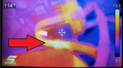
One other item to mention is the transmission fluid temperature sensor (Figure 13), which happens to be terminals 1 and 2 in both configurations. Terminal 1 is the signal wire with terminal 2 being the ground side. This temperature sensor, or the internal wiring harness that plugs into the sensor, is known to fail. It can produce codes P0711 (Rationality), P0712 (Circuit Low) and P0713 (Circuit High). This sensor will affect shift and TCC scheduling as well as shift feel. Correct TFT readings are also needed to ensure correct fluid levels as the level needs to be checked between 158-176° F.
Using the resistance specifications from the case connector, checking the sensor at the case connector and then again directly on the sensor itself will usually locate the problem. The sensor itself can be purchased separately for between $16 and $20, part No. 46386-3A050. The wiring harness is a bit more expensive. It can be purchased for between $160 and $200 dollars. The part number is 46308-3A550.
Subscribe to Motor Age and receive articles like this every month…absolutely free. Click here